Reset and interrupt handling, Reset sources – Rainbow Electronics AT90S1200 User Manual
Page 12
12
AT90S1200
0838H–AVR–03/02
Reset and Interrupt
Handling
The AT90S1200 provides three different interrupt sources. These interrupts and the
separate reset vector, each have a separate program vector in the program memory
space. All the interrupts are assigned individual enable bits that must be set (one)
together with the I-bit in the Status Register in order to enable the interrupt.
The lowest addresses in the program memory space are automatically defined as the
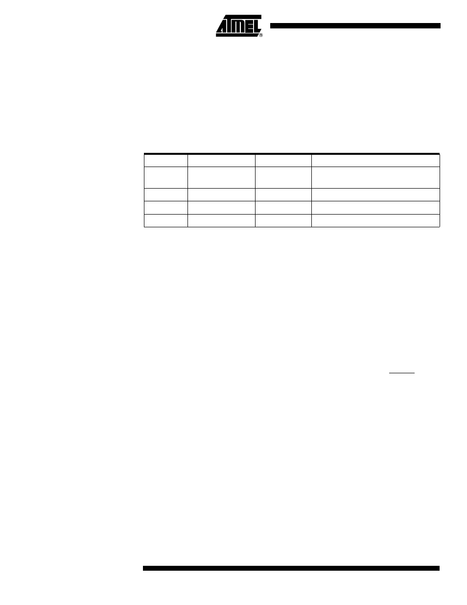
Reset and Interrupt vectors. The complete list of vectors is shown in Table 2. The list
also determines the priority levels of the different interrupts. The lower the address the
higher is the priority level. RESET has the highest priority, and next is INT0 (the External
Interrupt Request 0), etc.
The most typical and general program setup for the Reset and Interrupt Vector
Addresses are:
Address
Labels
Code
Comments
$000
rjmp
RESET
; Reset Handler
$001
rjmp
EXT_INT0
; IRQ0 Handler
$002
rjmp
TIM0_OVF
; Timer0 Overflow Handler
$003
rjmp
ANA_COMP
; Analog Comparator Handler
;
$004
MAIN:
; Main program start
…
…
… …
Reset Sources
The AT90S1200 has three sources of reset:
•
Power-on Reset. The MCU is reset when the supply voltage is below the power-on
Reset threshold (V
POT
).
•
External Reset. The MCU is reset when a low level is present on the RESET pin for
more than 50 ns.
•
Watchdog Reset. The MCU is reset when the Watchdog Timer period expires and
the Watchdog is enabled.
During Reset, all I/O registers are then set to their initial values, and the program starts
execution from address $000. The instruction placed in address $000 must be an RJMP
(relative jump) instruction to the reset handling routine. If the program never enables an
interrupt source, the interrupt vectors are not used, and regular program code can be
placed at these locations. The circuit diagram in Figure 13 shows the reset logic. Table 3
defines the timing and electrical parameters of the reset circuitry. Note that Power-on
Reset timing is clocked by the internal RC Oscillator. Refer to characterization data for
RC Oscillator frequency at other V
CC
voltages.
Table 2. Reset and Interrupt Vectors
Vector No.
Program Address
Source
Interrupt Definition
1
$000
RESET
Hardware Pin, Power-on Reset and
Watchdog Reset
2
$001
INT0
External Interrupt Request 0
4
$002
TIMER0, OVF0
Timer/Counter0 Overflow
5
$003
ANA_COMP
Analog Comparator