4 calibration, 5 debug mode – Rainbow Electronics AT42QT1040 User Manual
Page 10
10
9524A–AT42–03/09
AT42QT1040
4.4
Calibration
Calibration is the process by which the sensor chip assesses the background capacitance on
each channel. During calibration, a number of samples are taken in quick succession to get a
baseline for the channel’s reference value.
Calibration takes place ~50 ms after power is applied to the device. Calibration also occurs if the
Max On-duration is exceeded or a positive re-calibration occurs.
4.5
Debug Mode
An added feature to this device is a debug option whereby internal parameters from the IC can
be clocked out and monitored externally.
Debug mode is entered by shorting the CS3 capacitor (SNSK3 and SNS3 pins) on power-up
and removing the short within 5 seconds.
Note:
If the short is not removed within 5 seconds, debug mode is still entered, but with
Channel 3 unusable until a re-calibration occurs. Note that as Channel 3 will show up as
being in detect, a recalibration will occur after Max On-duration (~30 seconds).
Debug CLK pin (OUT0) and Debug Data pin (OUT1) float while debug data is not being output
and are driven outputs once debug output starts (that is, not open drain).
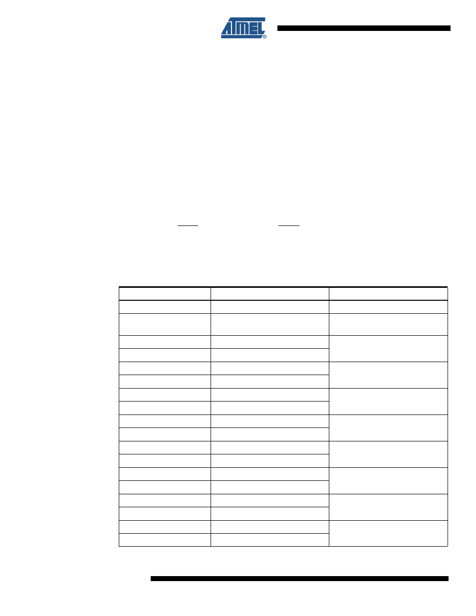
The serial data is clocked out at a rate of ~200 kHz, MSB first, as in
Table 4-3.
Serial Data Output
Byte
Purpose
Notes
0
Frame Number
Framing index number 0-255
1
Chip Version
Upper nibble: major revision
Lower nibble: minor revision
2
Reference 0 Low Byte
Unsigned 16-bit integer
3
Reference 0 High Byte
4
Reference 1 Low Byte
Unsigned 16-bit integer
5
Reference 1 High Byte
6
Reference 2 Low Byte
Unsigned 16-bit integer
7
Reference 2 High Byte
8
Reference 3 Low Byte
Unsigned 16-bit integer
9
Reference 3 High Byte
10
Signal 0 Low Byte
Unsigned 16-bit integer
11
Signal 0 High Byte
12
Signal 1 Low Byte
Unsigned 16-bit integer
13
Signal 1 High Byte
14
Signal 2 Low Byte
Unsigned 16-bit integer
15
Signal 2 High Byte
16
Signal 3 Low Byte
Unsigned 16-bit integer
17
Signal 3 High Byte