Ata6830, Stepping motor driver, Data communication – Rainbow Electronics ATA6830 User Manual
Page 6
6
ATA6830
4575B–BCD–01/03
Stepping Motor Driver
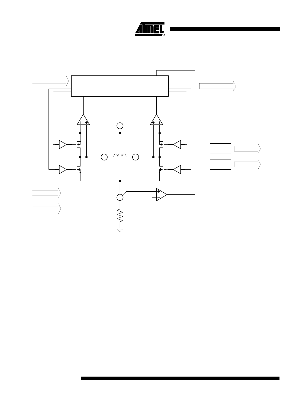
Figure 5.
Stepping Motor Driver
Figure 5 shows the diagram of one H-bridge driver stage. It consists of two NMOS and
two PMOS power transistors. An external shunt is used for measuring the current flow-
ing through the motor coil. Additional comparators and current sensing circuitry is
integrated for error detection.
Data Communication
The circuit receives all commands for the stepping motor via a single wire bus. In idle
mode the bus pin is pulled up by an internal current source near to VBAT voltage. Dur-
ing the transmission the external transmitter has to pull down the bus level to send
information about data and clock timing. The used baud rate has to be about 2400 baud.
Because of oscillator tolerances a synchronization sequence has to be sent at the
beginning of data transfer.
Figure 6 shows the pattern used for this sequence. The circuit uses the 1-0-1-0
sequences for adjusting the internal bit time. Later on during data transfer every 1-0-1-0
sequence coming up randomly is used for resynchronization. Thus all tolerances that
occur during operation will be eliminated.
To obtain a synchronization of up to 15% oscillator tolerance the pattern has to be sent
at least 4 times.
Shunt
VBAT
SM1x
SM2x
SRx
Vref
Stepper Motor Control
Temperature
Warning
Temperature
Shutdown
Clk
Reset
Error Signals
Driver Logic
Temp. Shutdown
Temp. Warning