Ata6830, Electrical characteristics (continued), Soldering recommendations – Rainbow Electronics ATA6830 User Manual
Page 19
19
ATA6830
4575B–BCD–01/03
7.2
Delay time
2 following
commands
22
T
D
5
ms
C, D
7.3
Pause time
Between high and low
byte
22
T
P
0
µs
C, D
7.4
Clamping time
Bus error clamping
22
Tcl
3
s
C, D
8
Logic
8.1
Reference run
detection
Commands in series
to execute first
reference run
Ref3
3
3
3
cmd
(1)
D
8.2
Synchronization
15% oscillator
tolerance
Sync
4
cmd
(1)
D
9
Thermal Values
9.1
Thermal prewarning
T_150
150
°
C
B
9.2
Hysteresis
Thermal prewarning
T_150
HYS
10
°
C
B
9.3
Thermal shut down
T_160
160
°
C
B
9.5
Thermal current
boost
T_0
0
°
C
B
9.6
Hysteresis
Thermal currrent
boost
T_0_HYS
10
°
C
B
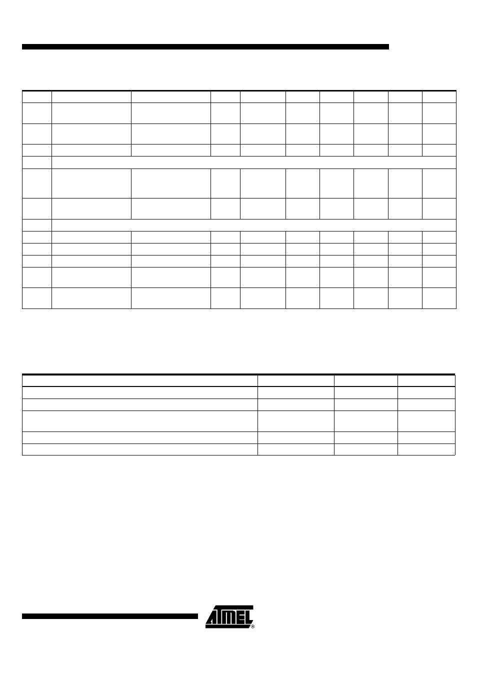
Electrical Characteristics (Continued)
No.
Parameters
Test Conditions
Pin
Symbol
Min.
Typ.
Max.
Unit
Type*
*) Type means: A = 100% tested, B = 100% correlation tested, C = Characterized on samples, D = Design parameter
Note:
1. cmd = command
Soldering Recommendations
Parameters
Symbol
Value
Unit
Maximum heating rate
T
D
1 to 3
°
C/s
Peak temperature in preheat zone
T
PH
100 to 140
°
C
Duration of time above melting point of solder
t
MP
minimum 10
maximum 75
s
Peak reflow temperature
T
Peak
220 to 225
°
C
Maximum cooling rate
T
Peak
2 to 4
°
C/s