Ata6830, Functional description, Analog blocks – Rainbow Electronics ATA6830 User Manual
Page 4
4
ATA6830
4575B–BCD–01/03
Functional Description
Analog Blocks
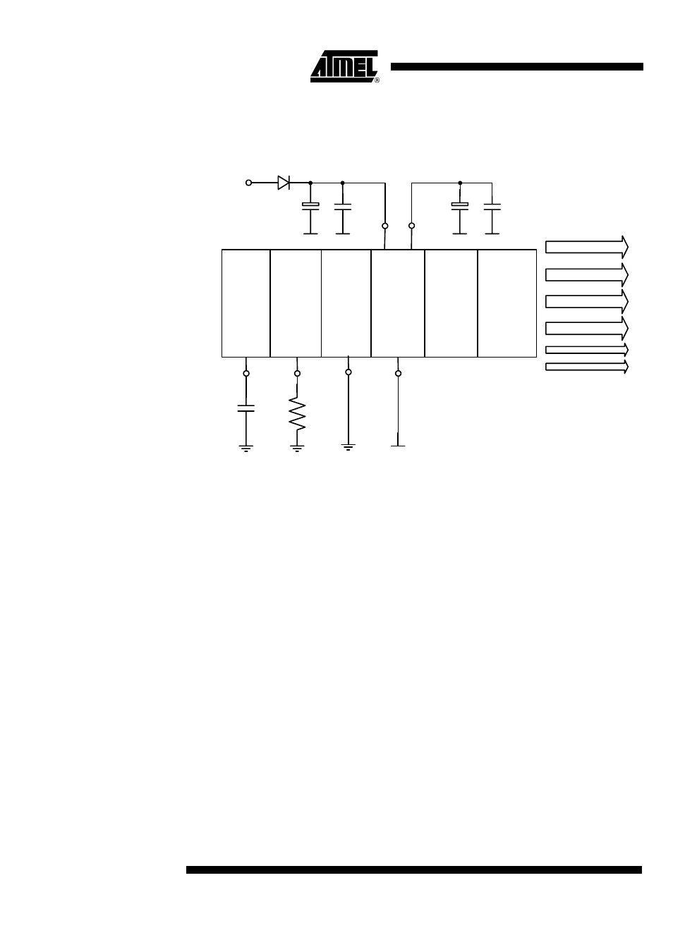
Figure 3.
Analog Blocks
The circuit contains an integrated 5 V regulator to supply the internal logic and analog
circuit blocks. The regulator uses an adjusted bandgap as voltage reference. Also all
other parts that require an excellent voltage reference, such as the voltage monitoring
block refer to the bandgap.
The bias generator derives its accurate currents from an external reference resistor. The
oscillator is used for clocking the digital system. All timings like the baud rate, the step
duration and the chopper frequency are determined from it. An external capacitor is
used for generating the frequency.
The voltage monitoring enables the circuit to drive the stepping motor at different battery
voltage levels. According to the battery voltage the stepping motor will be accelerated to
a maximum step velocity. In case of under or over voltage the motor will shut off. A tem-
perature monitoring is used for shut off at overtemperature conditions and current boost
in case of low temperature.
Oscillator
Bias
Generator
Bandgap
Voltage
Regulator
Voltage
Supervisor
COS
RSET
AGND
VSS
VDD
VBAT
Temperature
Supervisor
Bias
Clock
Supply
Reset
Voltage Levels
Temperature Levels