Low-current i – Rainbow Electronics DS1342 User Manual
Page 9
Low-Current I
2
C RTCs for High-ESR Crystals
DS1341/DS1342
9
known state by holding SCL low for t
TIMEOUT
. Doing so
limits the minimum frequency at which the I
2
C interface
can be operated. If data is being written to the device
when the interface timeout is exceeded, prior to the
acknowledge, the incomplete byte of data is not written.
Clock and Calendar (00h–06h)
The time and calendar information is obtained by read-
ing the appropriate register bytes. The RTC registers are
illustrated in Table 1. The time and calendar are set or
initialized by writing the appropriate register bytes. The
contents of the time and calendar registers are in the
binary-coded decimal (BCD) format. The Day register
increments at midnight and rolls over from 7 to 1. Values
that correspond to the day-of-week are user-defined
but must be sequential (i.e., if 1 equals Sunday, then 2
equals Monday, and so on). The CENT bit in the Month
register toggles when the Years register rolls over from
99 to 00. Illogical time and date entries result in an unde-
fined operation.
The DS1341/DS1342 can be run in either 12hr or 24hr
mode. Bit 6 of the Hours register is defined as the 12hr
or 24hr mode select bit. When high, the 12hr mode is
selected. In the 12hr mode, bit 5 is the AM/PM bit, with
a content of 1 being PM. In the 24hr mode, bit 5 is the
second bit of the 10hr field. The century bit (bit 7 of the
Month register) is toggled when the Years register incre-
ments from 99 to 00. On a power-on reset (POR), the
time and date are set to 00:00:00 00/01/01 and the Day
register is set to 01.
Alarms (07h–0Dh)
The DS1341/DS1342 contain two time-of-day/date
alarms. Alarm 1 can be set by writing to registers 07h–
0Ah. Alarm 2 can be set by writing to registers 0Bh–0Dh.
The alarms can be programmed to activate the CLKIN/
INTA or SQW/INTB outputs (see Table 5) on an alarm
match condition. Bit 7 of each of the time of day/date
alarm registers are mask bits. When all the mask bits for
each alarm are 0, an alarm only occurs when the values
in the timekeeping registers 00h–06h match the values
stored in the time of day/date alarm registers. The alarms
can also be programmed to repeat every second, min-
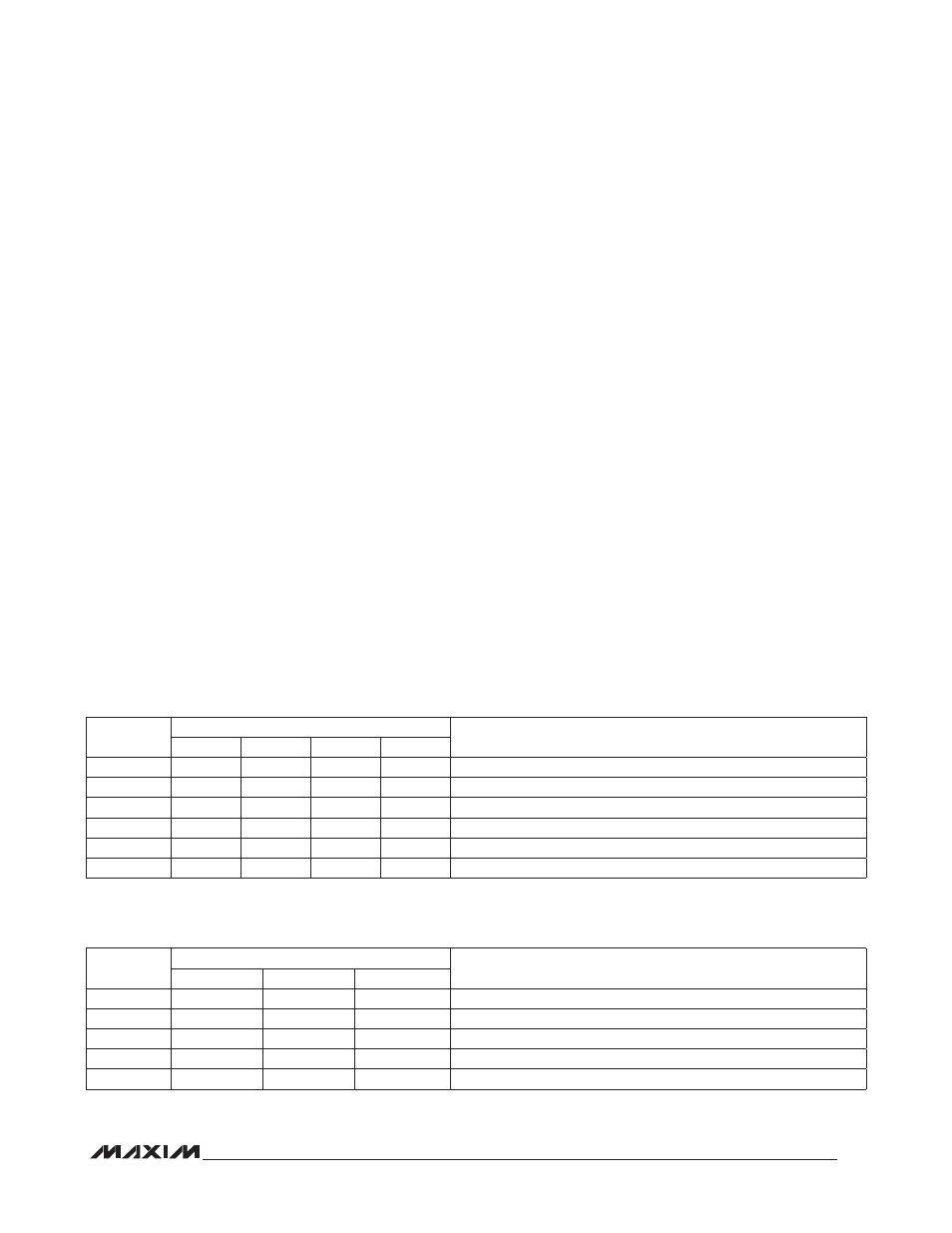
ute, hour, day, or date. Tables 2 and 3 show the possible
alarm settings. Configurations not listed in the tables
result in illogical operation. POR values are undefined.
The DY/DT bits (bit 6 of the alarm day/date registers)
control whether the alarm value stored in bits 0 to 5 of
that register reflects the day of the week or the date of
the month. If DY/DT is written to 0, the alarm is the result
Table 2. Alarm 1 Mask Bits
Table 3. Alarm 2 Mask Bits
X = Don’t care.
X = Don’t care.
DY/DT
ALARM 1 MASK BITS (BIT 7)
ALARM RATE
A1M4
A1M3
A1M2
A1M1
X
1
1
1
1
Alarm once per second.
X
1
1
1
0
Alarm when seconds match.
X
1
1
0
0
Alarm when minutes and seconds match.
X
1
0
0
0
Alarm when hours, minutes, and seconds match.
0
0
0
0
0
Alarm when date, hours, minutes, and seconds match.
1
0
0
0
0
Alarm when day, hours, minutes, and seconds match.
DY/DT
ALARM 2 MASK BITS (BIT 7)
ALARM RATE
A2M4
A2M3
A2M2
X
1
1
1
Alarm once per minute (00 second of every minute).
X
1
1
0
Alarm when minutes match.
X
1
0
0
Alarm when hours and minutes match.
0
0
0
0
Alarm when date, hours, and minutes match.
1
0
0
0
Alarm when day, hours, and minutes match.