Low-current i, Table 1. register map – Rainbow Electronics DS1342 User Manual
Page 8
Low-Current I
2
C RTCs for High-ESR Crystals
DS1341/DS1342
8
Register Map
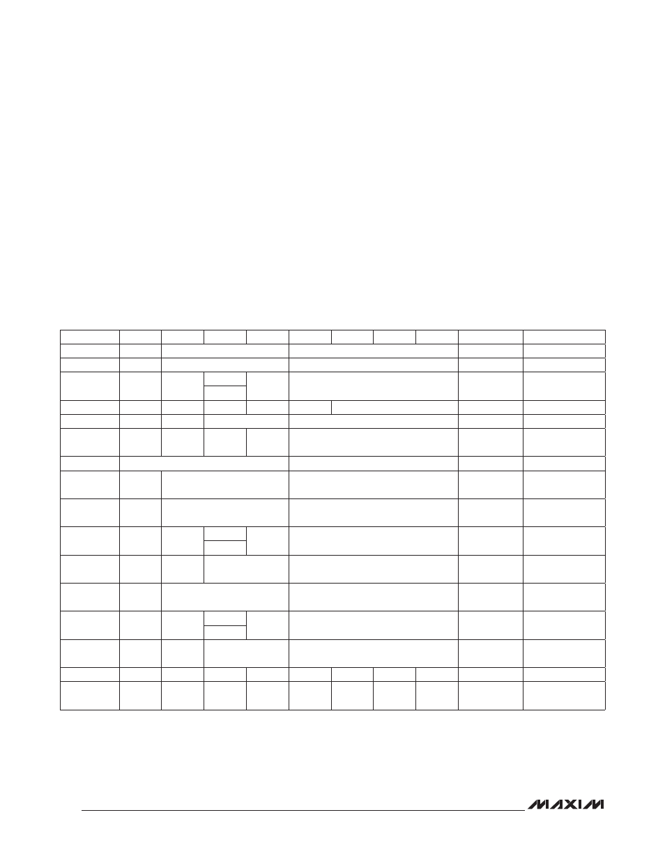
Table 1 shows the map for the DS1341/DS1342 regis-
ters. During a multibyte access, if the address pointer
reaches the end of the register space (0Fh), it wraps
around to location 00h. On either an I
2
C START or
address pointer incrementing to location 00h, the current
time is transferred to a second set of registers. The time
information is read from these secondary registers while
the clock continues to run. This eliminates the need to
reread the registers in case the main registers update
during a read.
I
2
C Interface
The I
2
C interface is guaranteed to operate when V
CC
is
between 1.8V and 5.5V and the EOSC bit is 0. The I
2
C
interface is accessible whenever V
CC
is at a valid level.
To prevent invalid device operation, the I
2
C interface
should not be accessed when V
CC
is below +1.8V.
If a microcontroller connected to the DS1341/DS1342
resets during I
2
C communications, it is possible that the
microcontroller and the DS1341/DS1342 could become
unsynchronized. When the microcontroller resets, the
DS1341/DS1342 I
2
C interface can be placed into a
Table 1. Register Map
Note: Bits listed as 0 always read back as 0 and cannot be written to a 1.
ADDRESS
BIT 7
BIT 6
BIT 5
BIT 4
BIT 3
BIT 2
BIT 1
BIT 0
FUNCTION
RANGE
00h
0
10 Seconds
Seconds
Seconds
00–59
01h
0
10 Minutes
Minutes
Minutes
00–59
02h
0
12/24
AM/PM
10hr
Hour
Hours
1–12+AM/PM
00–23
10hr
03h
0
0
0
0
0
Day
Day
1–7
04h
0
0
10 Date
Date
Date
01–31
05h
CENT
0
0
10 MO
Month
Month/
Century
01–12 + Century
06h
10 Year
Year
Year
00–99
07h
A1M1
10 Seconds
Seconds
Alarm 1
Seconds
00–59
08h
A1M2
10 Minutes
Minutes
Alarm 1
Minutes
00–59
09h
A1M3
12/24
AM/PM
10hr
Hour
Alarm 1
Hours
1–12 + AM/PM
00–23
10hr
0Ah
A1M4
DY/DT
10 Date
Day,
Date
Alarm 1 Day,
Alarm 1 Date
1–7
1–31
0Bh
A2M2
10 Minutes
Minutes
Alarm 2
Minutes
00–59
0Ch
A2M3
12/24
AM/PM
10hr
Hour
Alarm 2
Hours
1–12 + AM/PM
00–23
10hr
0Dh
A2M4
DY/DT
10 Date
Day,
Date
Alarm 2 Day,
Alarm 2 Date
1–7
1–31
0Eh
EOSC
0
EGFIL
RS2
RS1
INTCN
A2IE
A1IE
Control
—
0Fh
OSF
DOSF
LOS
CLKSEL2 CLKSEL1
ECLK
A2F
A1F
Control/
Status
—