Low-current i – Rainbow Electronics DS1342 User Manual
Page 4
Low-Current I
2
C RTCs for High-ESR Crystals
DS1341/DS1342
4
Note 11: CB is the total capacitance of one bus line, including all connected devices, in pF.
Note 12: The parameter tOSF is the period of time the oscillator must be stopped for the OSF flag to be set over the voltage
range of 2.4V P V
CC
P V
CCMAX
.
Note 13: The DS1341/DS1342 can detect any single SCL clock held low longer than t
TIMEOUTMIN
. The devices’ I
2
C interface is
in reset state and can receive a new START condition when SCL is held low for at least t
TIMEOUTMAX
. Once the device
detects this condition, the SDA output is released. The oscillator must be running for this function to work.
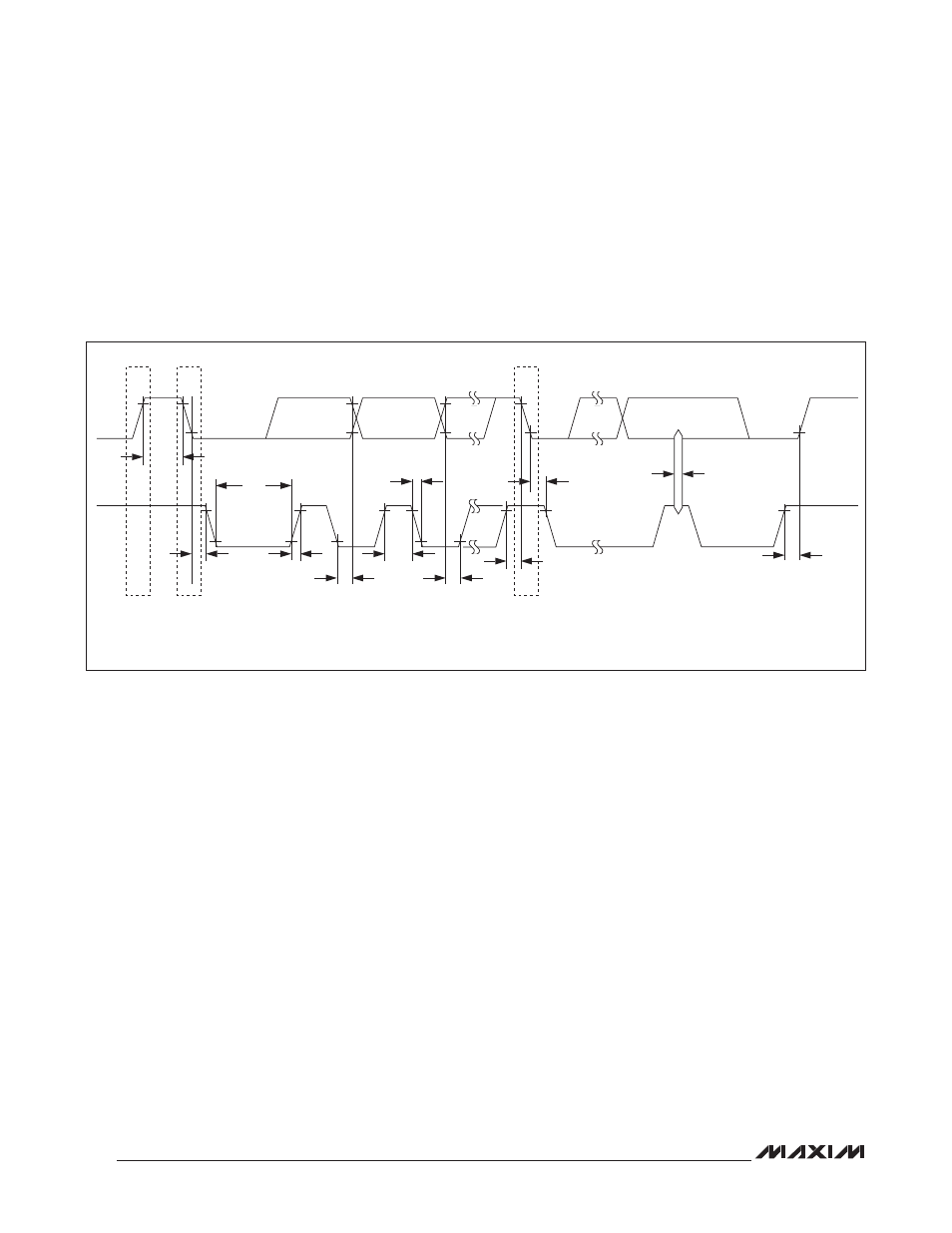
Figure 1. Data Transfer on I
2
C Serial Bus
SCL
NOTE: TIMING IS REFERENCED TO V
ILMAX
AND V
IHMIN
.
SDA
STOP
START
REPEATED
START
t
BUF
t
HD:STA
t
HD:DAT
t
SU:DAT
t
SU:STO
t
HD:STA
t
SP
t
SU:STA
t
HIGH
t
R
t
F
t
LOW
- MAX6869 (17 pages)
- TNY-A9260-C01 (5 pages)
- MAX34441 (53 pages)
- MAX4912 (13 pages)
- QIL-A9260-C11 (20 pages)
- QIL-A9260-C11 (1 page)
- QIL-A9260-C11 (34 pages)
- USB-A9263-C02 (1 page)
- DAB-GPS-C01 (15 pages)
- DAB-GPS-C01 (28 pages)
- DAB-CAM-C01 (27 pages)
- DAB-WLS-C01 (WiFi) (20 pages)
- USB-A9G20-C01 (1 page)
- MAX34440 (43 pages)
- SBC35-A9260-C12 (28 pages)
- SBC35-A9260-C12 (1 page)
- MAX16024 (17 pages)
- USB-A9G20-C11 (5 pages)
- DAB-IMU-C01 (20 pages)
- MAX16021 (21 pages)
- DAB-WLS-C11 (BlueTooth) (2 pages)
- SBC35-A9G20-C11 (24 pages)
- MAX16054 (9 pages)
- MAX14525 (7 pages)
- MAX16066 (61 pages)
- USB-A9260-C12 (1 page)
- DS1803 (11 pages)
- DS12887A (2 pages)
- DS1339 (18 pages)
- DS1858 (22 pages)
- DS1267 (12 pages)
- DS12С887A (2 pages)
- DS1804 (7 pages)
- DS1091L (6 pages)
- DS1669S (10 pages)
- DS1867 (14 pages)
- DS1087L (12 pages)
- DS4026 (13 pages)
- DS1286 (13 pages)
- DS1801 (10 pages)
- DS1254 (17 pages)
- DS17887 (38 pages)
- DS1691 (4 pages)
- DS1615 (24 pages)
- DS1868 (14 pages)