Low-current i, C communication, See figure 6 for an i – Rainbow Electronics DS1342 User Manual
Page 13
Low-Current I
2
C RTCs for High-ESR Crystals
DS1341/DS1342
13
DS1341/DS1342s’ slave address is D0h and cannot
be modified by the user. When the R/W bit is 0 (such
as in D0h), the master is indicating it writes data to the
slave. If R/W = 1 (D1h in this case), the master is indi-
cating it wants to read from the slave. If an incorrect
slave address is written, the DS1341/DS1342 assume
the master is communicating with another I
2
C device
and ignore the communication until the next START
condition is sent.
Memory Address: During an I
2
C write operation, the
master must transmit a memory address to identify
the memory location where the slave is to store the
data. The memory address is always the second byte
transmitted during a write operation following the
slave address byte.
I
2
C Communication
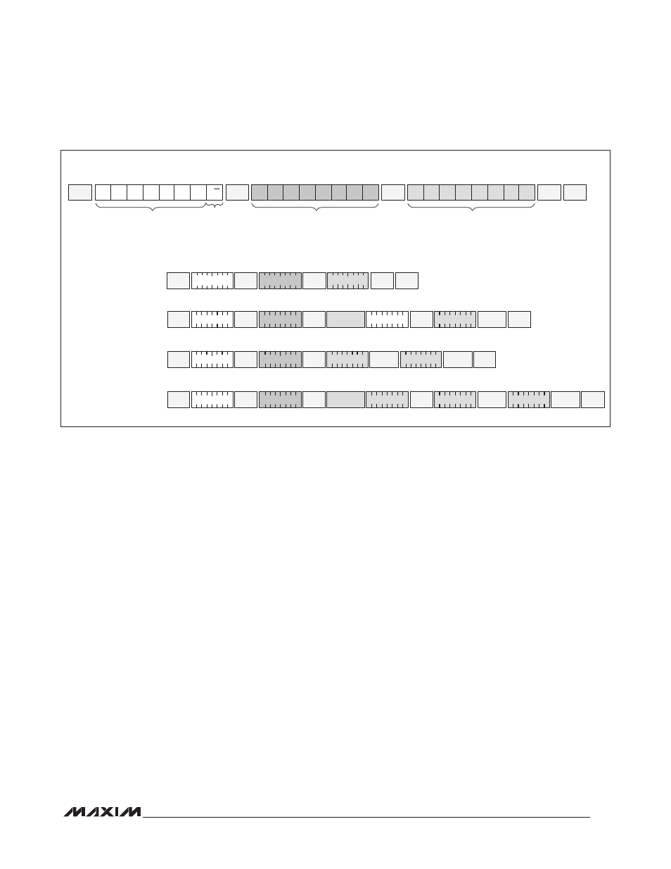
See Figure 6 for an I
2
C communication example.
Writing a Single Byte to a Slave: The master must
generate a START condition, write the slave address
byte (R/W = 0), write the memory address, write
the byte of data, and generate a STOP condition.
Remember the master must read the slave’s acknowl-
edgment during all byte write operations.
Writing Multiple Bytes to a Slave: To write multiple
bytes to a slave, the master generates a START con-
dition, writes the slave address byte (R/W = 0), writes
the starting memory address, writes multiple data
bytes, and generates a STOP condition.
Reading a Single Byte from a Slave: Unlike the write
operation that uses the specified memory address
byte to define where the data is to be written, the read
operation occurs at the present value of the memory
address counter. To read a single byte from the slave,
the master generates a START condition, writes the
slave address byte with R/W = 1, reads the data byte
with a NACK to indicate the end of the transfer, and
generates a STOP condition. However, since requir-
ing the master to keep track of the memory address
counter is impractical, use the method for manipulat-
ing the address counter for reads.
Manipulating the Address Counter for Reads: A
dummy write cycle can be used to force the address
counter to a particular value. To do this the mas-
ter generates a START condition, writes the slave
address byte (R/W = 0), writes the memory address
where it desires to read, generates a repeated START
condition, writes the slave address byte (R/W = 1),
Figure 6. I
2
C Transactions
SLAVE
ADDRESS
START
START
1
1
0
1
0
0
0
SLAVE
ACK
SLAVE
ACK
SLAVE
ACK
R/W
MSB
LSB
MSB
LSB
MSB
LSB
b7
b6
b5
b4
b3
b2
b1
b0
READ/
WRITE
REGISTER ADDRESS
b7
b6
b5
b4
b3
b2
b1
b0
DATA
STOP
SINGLE BYTE WRITE
-WRITE CONTROL REGISTER
TO 18h
MULTIBYTE WRITE
-WRITE DATE REGISTER
TO "02" AND MONTH
REGISTER TO "11"
SINGLE BYTE READ
-READ CONTROL REGISTER
MULTIBYTE READ
-READ ALARM 2 HOURS
AND DATE VALUES
START
REPEATED
START
D1h
MASTER
NACK
STOP
1 1 0 1 0 0 0 0
0 0 0 0 1 1 1 0
0Eh
1 1 0 1 0 0 0 1
1 1 0 1 0 0 0 0
0 0 0 0 1 1 1 0
D0h
0Eh
STOP
VALUE
START 1 1 0 1 0 0 0 0
0 0 0 0 0 1 0 0
D0h
04h
DATA
MASTER
NACK
STOP
VALUE
DATA
02h
18h
EXAMPLE I
2
C TRANSACTIONS
TYPICAL I
2
C WRITE TRANSACTION
0 0 0 1 1 0 0 0
0 0 0 0 0 0 1 0
D0h
A)
C)
B)
D)
SLAVE
ACK
SLAVE
ACK
SLAVE
ACK
SLAVE
ACK
SLAVE
ACK
SLAVE
ACK
SLAVE
ACK
REPEATED
START
D1h
MASTER
ACK
1 1 0 1 0 0 0 1
VALUE
DATA
SLAVE
ACK
SLAVE
ACK
SLAVE
ACK
START 1 1 0 1 0 0 0 0
0 0 0 0 1 1 0 0
D0h
0Ch
SLAVE
ACK
SLAVE
ACK
STOP
11h
0 0 0 1 0 0 0 1
SLAVE
ACK