Uart control register – ucr – Rainbow Electronics AT90S2313 User Manual
Page 46
46
AT90S2313
0839I–AVR–06/02
• Bit 4 – FE: Framing Error
This bit is set if a Framing Error condition is detected (i.e., when the stop bit of an incom-
ing character is zero).
The FE bit is cleared when the stop bit of received data is one.
• Bit 3 – OR: OverRun
This bit is set if an OverRun condition is detected (i.e., when a character already present
in the UDR Register is not read before the next character has been shifted into the
Receiver Shift Register). The OR bit is buffered, which means that it will be set once the
valid data still in UDRE is read.
The OR bit is cleared (zero) when data is received and transferred to UDR.
• Bits 2..0 – Res: Reserved Bits
These bits are reserved bits in the AT90S2313 and will always read as zero.
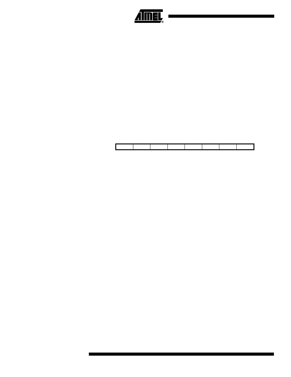
UART Control Register – UCR
• Bit 7 – RXCIE: RX Complete Interrupt Enable
When this bit is set (one), a setting of the RXC bit in USR will cause the Receive Com-
plete Interrupt routine to be executed provided that global interrupts are enabled.
• Bit 6 – TXCIE: TX Complete Interrupt Enable
When this bit is set (one), a setting of the TXC bit in USR will cause the Transmit Com-
plete Interrupt routine to be executed provided that global interrupts are enabled.
• Bit 5 – UDRIE: UART Data Register Empty Interrupt Enable
When this bit is set (one), a setting of the UDRE bit in USR will cause the UART Data
Register Empty Interrupt routine to be executed provided that global interrupts are
enabled.
• Bit 4 – RXEN: Receiver Enable
This bit enables the UART Receiver when set (one). When the Receiver is disabled, the
RXC, OR and FE Status Flags cannot become set. If these flags are set, turning off
RXEN does not cause them to be cleared.
• Bit 3 – TXEN: Transmitter Enable
This bit enables the UART Transmitter when set (one). When disabling the Transmitter
while transmitting a character, the Transmitter is not disabled before the character in the
Shift Register plus any following character in UDR has been completely transmitted.
• Bit 2 – CHR9: 9 Bit Characters
When this bit is set (one), transmitted and received characters are nine bits long plus
start and stop bits. The ninth bit is read and written by using the RXB8 and TXB8 bits in
UCR, respectively. The ninth data bit can be used as an extra stop bit or a parity bit.
Bit
7
6
5
4
3
2
1
0
$0A ($2A)
RXCIE
TXCIE
UDRIE
RXEN
TXEN
CHR9
RXB8
TXB8
UCR
Read/Write
R/W
R/W
R/W
R/W
R/W
R/W
R
W
Initial value
0
0
0
0
0
0
1
0