General interrupt flag register – gifr, Timer/counter interrupt mask register – timsk – Rainbow Electronics AT90S2313 User Manual
Page 23
23
AT90S2313
0839I–AVR–06/02
General Interrupt FLAG
Register – GIFR
• Bit 7 – INTF1: External Interrupt Flag1
When an edge on the INT1 pin triggers an interrupt request, the corresponding Interrupt
Flag, INTF1, becomes set (one). If the I-bit in SREG and the corresponding interrupt
enable bit, INT1 bit in GIMSK, are set (one), the MCU will jump to the Interrupt Vector.
The flag is cleared when the interrupt routine is executed. Alternatively, the flag can be
cleared by writing a logical “1” to it. The flag is always cleared when INT1 is configured
as level interrupt.
• Bit 6 – INTF0: External Interrupt Flag0
When an edge on the INT0 pin triggers an interrupt request, the corresponding Interrupt
Flag, INTF0, becomes set (one). If the I-bit in SREG and the corresponding interrupt
enable bit, INT0 bit in GIMSK, are set (one), the MCU will jump to the Interrupt Vector.
The flag is cleared when the interrupt routine is executed. Alternatively, the flag can be
cleared by writing a logical “1” to it. The flag is always cleared when INT0 is configured
as level interrupt.
• Bits 5..0 – Res: Reserved Bits
These bits are reserved bits in the AT90S2313 and always read as zero.
Note that external level interrupt does not have a flag, and will only be remembered for
as long as the interrupt condition is active.
Timer/Counter Interrupt Mask
Register – TIMSK
• Bit 7 – TOIE1: Timer/Counter1 Overflow Interrupt Enable
When the TOIE1 bit is set (one) and the I-bit in the Status Register is set (one), the
Timer/Counter1 Overflow Interrupt is enabled. The corresponding interrupt (at vector
$005) is executed if an overflow in Timer/Counter1 occurs (i.e., when the TOV1 bit is set
in the Timer/Counter Interrupt Flag Register [TIFR]).
• Bit 6 – OCIE1A: Timer/Counter1 Output Compare Match Interrupt Enable
When the OCIE1A bit is set (one) and the I-bit in the Status Register is set (one), the
Timer/Counter1 Compare Match Interrupt is enabled. The corresponding interrupt (at
vector $004) is executed if a compare match in Timer/Counter1 occurs (i.e., when the
OCF1A bit is set in the Timer/Counter Interrupt Flag Register [TIFR]).
• Bit 5,4 – Res: Reserved Bits
These bits are reserved bits in the AT90S2313 and always read as zero.
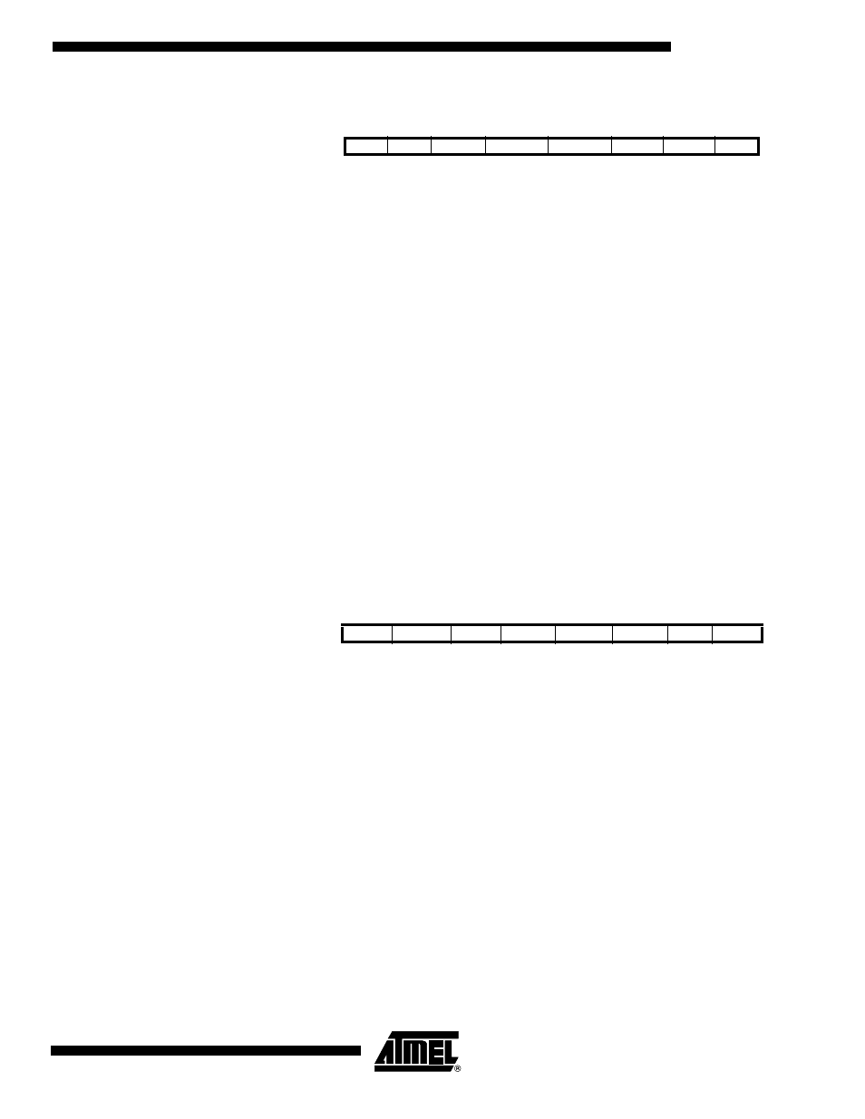
Bit
7
6
5
4
3
2
1
0
$3A ($5A)
INTF1
INTF0
–
–
–
–
–
–
GIFR
Read/Write
R/W
R/W
R
R
R
R
R
R
Initial value
0
0
0
0
0
0
0
0
Bit
7
6
5
4
3
2
1
0
$39 ($59)
TOIE1
OCIE1A
–
–
TICIE1
–
TOIE0
–
TIMSK
Read/Write
R/W
R/W
R
R
R/W
R
R/W
R
Initial value
0
0
0
0
0
0
0
0