Bit timer/counter1 – Rainbow Electronics AT90S2313 User Manual
Page 30
30
AT90S2313
0839I–AVR–06/02
16-bit Timer/Counter1
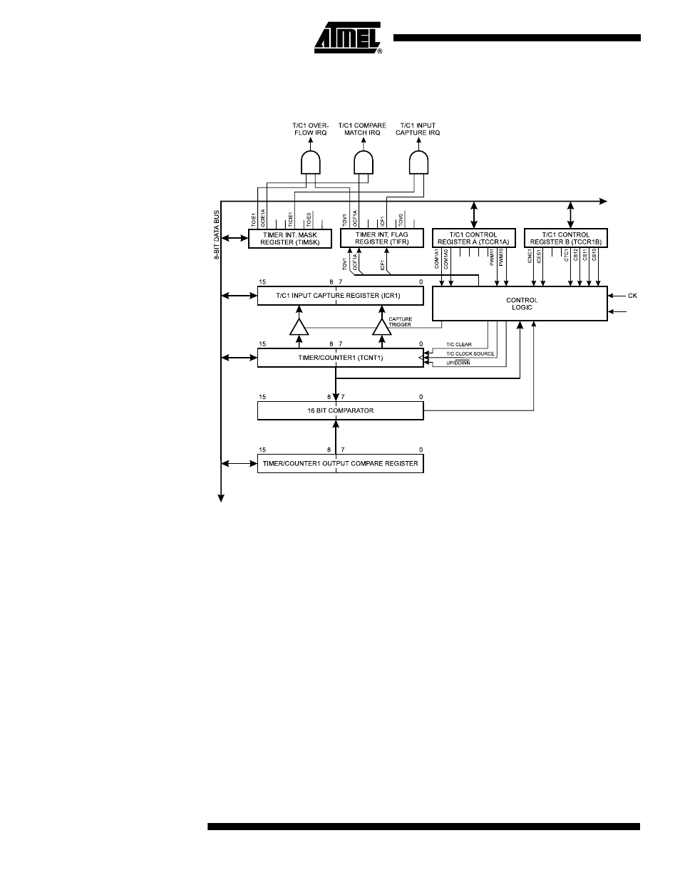
Figure 30 shows the block diagram for Timer/Counter1.
Figure 30. Timer/Counter1 Block Diagram
The 16-bit Timer/Counter1 can select clock source from CK, prescaled CK or an exter-
nal pin. In addition, it can be stopped as described in the specification for the
Timer/Counter1 Control Register (TCCR1B). The different Status Flags (Overflow, Com-
pare Match and Capture Event) and control signals are found in the Timer/Counter
Interrupt Flag Register (TIFR). The interrupt enable/disable settings for Timer/Counter1
are found in the Timer/Counter Interrupt Mask Register (TIMSK).
When Timer/Counter1 is externally clocked, the external signal is synchronized with the
Oscillator frequency of the CPU. To assure proper sampling of the external clock, the
minimum time between two external clock transitions must be at least one internal CPU
clock period. The external clock signal is sampled on the rising edge of the internal CPU
clock.
The 16-bit Timer/Counter1 features both a high-resolution and a high-accuracy usage
with the lower prescaling opportunities. Similarly, the high prescaling opportunities
makes the Timer/Counter1 useful for lower speed functions or exact timing functions
with infrequent actions.
The Timer/Counter1 supports an Output Compare function using the Output Compare
Register 1A (OCR1A) as the data source to be compared to the Timer/Counter1 con-
tents. The Output Compare functions include optional clearing of the counter on
compare matches, and actions on the Output Compare pin 1 on compare matches.
T1