External reset, Watchdog reset, Interrupt handling – Rainbow Electronics AT90S2313 User Manual
Page 21
21
AT90S2313
0839I–AVR–06/02
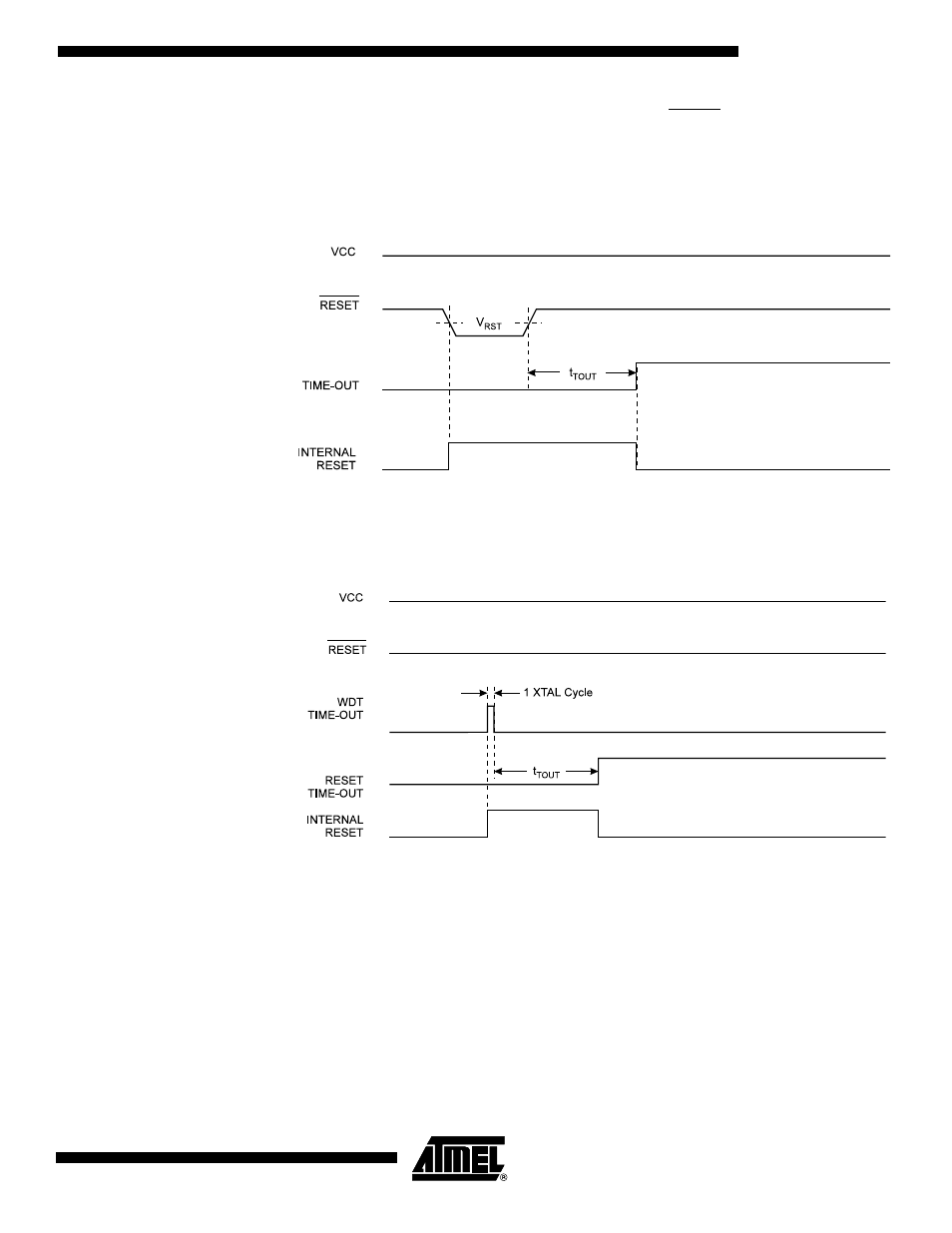
External Reset
An External Reset is generated by a low level on the RESET pin. Reset pulses longer
than 50 ns will generate a reset, even if the clock is not running. Shorter pulses are not
guaranteed to generate a reset. When the applied signal reaches the Reset Threshold
Voltage (V
RST
) on its positive edge, the delay timer starts the MCU after the Time-out
period t
TOUT
has expired.
Figure 26. External Reset during Operation
Watchdog Reset
When the Watchdog times out, it will generate a short reset pulse of one XTAL cycle
duration. On the falling edge of this pulse, the delay timer starts counting the Time-out
period t
TOUT
. Refer to page 37 for details on operation of the Watchdog.
Figure 27. Watchdog Reset during Operation
Interrupt Handling
The AT90S2313 has two 8-bit Interrupt Mask Control Registers: the GIMSK (General
Interrupt Mask Register) and the TIMSK (Timer/Counter Interrupt Mask Register).
When an interrupt occurs, the Global Interrupt Enable I-bit is cleared (zero) and all inter-
rupts are disabled. The user software can set (one) the I-bit to enable interrupts. The I-
bit is set (one) when a Return from Interrupt instruction (RETI) is executed.
For interrupts triggered by events that can remain static (e.g., the Output Compare
Register1 matching the value of Timer/Counter1), the Interrupt Flag is set when the
event occurs. If the Interrupt Flag is cleared and the interrupt condition persists, the flag
will not be set until the event occurs the next time.
When the Program Counter is vectored to the actual Interrupt Vector in order to execute
the interrupt handling routine, hardware clears the corresponding flag that generated the