Rainbow Electronics BTM -17х User Manual
Page 4
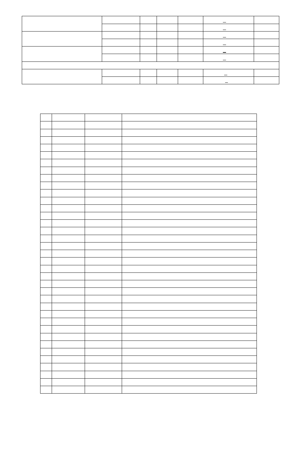
π/4 DQPSK
- -23 -
< -20
dB
Adjacent channel selectivity C/I
F=F
0
-2 MHz
8 DPSK
-
-20
-
< -13
dB
π/4 DQPSK
- -45 -
< -40
dB
Adjacent channel selectivity C/I
F=F
0
+3 MHz
8 DPSK
-
-45
-
< -33
dB
π/4 DQPSK
- -45 -
< -40
dB
Adjacent channel selectivity C/I
F=F
0
-5 MHz
8 DPSK
-
-45
-
< -33
dB
F
0
= 2405, 2441, 2477 MHz
π/4 DQPSK
-20
< -7
dB
Adjacent channel selectivity C/I
F=F
image
8 DPSK
-15
< 0
dB
BTM-160/170 Pins out Information
PIN NAME
TYPE
FUNCTION
1
GND
GND
Ground
2 RF_IO
Analogue
Antenna Interface
3 GND
GND
Ground
4
PIO(11)
Bi-directional
Programmable Input/Output line
5 PIO(10)
Bi-directional
Programmable Input/Output line
6 PIO(9)
Bi-directional
Programmable Input/Output line
7 PIO(8)
Bi-directional
Programmable Input/Output line
8 PIO(2)
Bi-directional
Programmable Input/Output line
9 AIO(1)
Bi-directional
Programmable Input/Output Line
10 GND
GND
Ground
11
VDD
Power
3.3V or 1.8V Power Supply Input
12
AIO(0)
Bi-directional
Programmable Input/Output Line , 32KHz sleep clock input
13
UART_TX
CMOS Input
UART Data Output
14
UART_RTS
CMOS Output
UART Request To Send (Active Low)
15
UART_RX
CMOS Output
UART Data Input
16
UART_CTS
CMOS Input
UART Clear To Send (Active Low)
17 USB_DP
Bi-directional
USB Data Plus
18 USB_DN
Bi-directional
USB Data Minus
19 PCM_CLK
Bi-directional
Synchronous Data Clock
20
PCM_IN
CMOS Input
Synchronous Data Input
21 PCM_OUT
CMOS Output
Synchronous Data Output
22 PCM_SYNC
Bi-directional
Synchronous Data Sync
23
VDD_USB
Power
3.3V Power Supply Input
24 PIO(7)
Bi-directional
Programmable Input/Output line
25 PIO(6)
Bi-directional
Programmable Input/Output line , CLK_REQ , WLAN_Ative/Ch_Data input
26 PIO(5)
Bi-directional
Programmable Input/Output line , USB_DETACH, BT_Ative output
27
PIO(4)
Bi-directional
Programmable Input / Output Line , USB_ON, BT_Priority/Ch_Clk Output
28 GND
GND
Ground
29
RESETB
CMOS input
Reset if low. Input debounced so must be low for >5ms to cause a reset
30
SPI_CSB
CMOS Input
Chip Select For Synchronous Serial Interface active low
31
SPI_MISO
CMOS Output
Serial Peripheral Interface Data Output
32
SPI_MOSI
CMOS Input
Serial Peripheral Interface Data Input
33
SPI_CLK
CMOS Input
Serial Peripheral Interface Clock
34 PIO(3)
Bi-directional
Programmable Input/Output Line , USB_WAKE_UP, CLK_REQ_IN
35
PIO(1)
Bi-directional
Programmable Input/Output Line , TX Enable
36
PIO(0)
Bi-directional
Programmable Input / Output Line , RX Enable