U2741b, Output power measurement – Rainbow Electronics U2741B User Manual
Page 5
5
U2741B
4733A–RKE–11/03
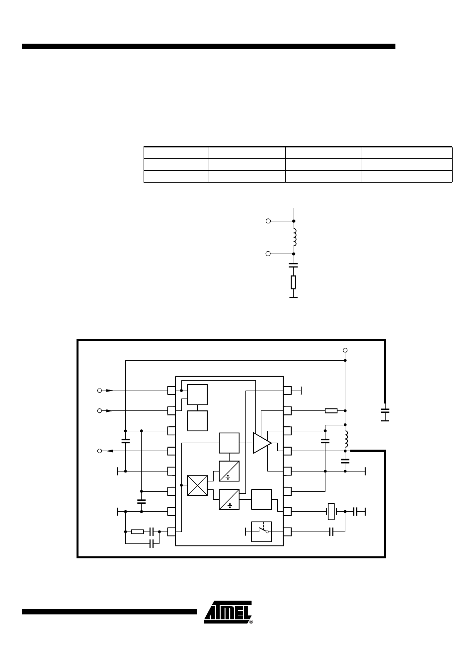
Output Power
Measurement
The output network [as shown in Figure 4] can be used for output power evaluation, the
exact values of L
10
and C
10
depend on the layout.
L
10
and C
10
form the transformation network to adopt the output impedance of the IC to
50
W
. Table 1 shows the values for an output power of 2 mW and an R
PWRSET
= 1.2 k
W
.
Figure 4. Measurement Output Network
Figure 5. Application Circuit
Table 1. Transformation Network
f/MHz
C10/pF
L10/nH
Z
Load_opt
/
W
315
2.7
56
260 + j330
433.92
1.8
33
185 + j268
PWRVCC
ANT
V
S
L
10
C
10
50
W
Z
Load-opt
16
1
2
3
4
5
6
7
8
15
14
13
12
11
10
9
64
f
PA
n
f
OR
Power
up
VCO
XTO
ASK
FSK
VCC
CLK
GND
LFVCC
LFGND
LF
DIVC
PWRSET
PWRVCC
ANT
PWRGND1
PWRGND2
XTO1
XTO2
C
5
R
PWRSET
L
Feed
C
Loop1
13.56 MHz
C
3
C
4
+V
S
= 2.0 ... 5.5 V
C
Loop2
C
7
C
1
C
2
R
4
ASK
FSK
CLK
3.39 MHz
C
6
U2741B
Antenna
- RC2000 (2 pages)
- Т7023 (12 pages)
- Т7024 (20 pages)
- RC2200 (17 pages)
- RF01 (26 pages)
- RC1090 (17 pages)
- U3741BM (32 pages)
- U3742BM (32 pages)
- RAM01 (7 pages)
- RF22 (92 pages)
- RC1180-MBUS (28 pages)
- RFM01 (8 pages)
- RF12B (36 pages)
- RC1290 (17 pages)
- RC2300-ZNM (1 page)
- RF12 (31 pages)
- T48C862-R3 (107 pages)
- RF02 (24 pages)
- T48C862-R8 (107 pages)
- RFM12 (10 pages)
- U3745BM (29 pages)
- T5744 (19 pages)
- RFM12B (10 pages)
- U2745B (9 pages)
- T48C862-R4 (107 pages)
- RA01 (19 pages)
- T5754 (11 pages)
- RFM02 (8 pages)
- RC2100 (22 pages)
- RF модули диапазона ISM (4 pages)
- T5761 (35 pages)
- BTM -17х (5 pages)
- ATA8401 (12 pages)
- BTM -22х (7 pages)
- AT86RF231 (180 pages)
- ATA5575M1 (7 pages)
- AT88RF1354 (50 pages)
- ATA5812 (90 pages)
- AT86RF401 (50 pages)
- AT76C551 (77 pages)
- BTM -250 (6 pages)
- AT75C310 (132 pages)
- AT75C320 (13 pages)
- BTM -140 (6 pages)