Mfr_vout_peak (d4h), Mfr_iout_peak (d5h), Mfr_temperature_peak (d6h) – Rainbow Electronics MAX34440 User Manual
Page 36: Mfr_vout_min (d7h), Mfr_fault_response (d9h), Table 22. mfr_fault_response
PMBus 6-Channel Power-Supply Manager
MAX34440
36
MFR_VOUT_PEAK (D4h)
The MFR_VOUT_PEAK command returns the maximum actual measured output voltage. To reset this value to 0, write to this
command with a data value of 0. Any values written to this command are used as a comparison for future peak updates. The
2 data bytes are in DIRECT format.
MFR_IOUT_PEAK (D5h)
The MFR_IOUT_PEAK command returns the maximum measured current. To reset this value to 0, write to this com-
mand with a data value of 0. Any values written to this command are used as a comparison for future peak updates.
The 2 data bytes are in DIRECT format.
MFR_TEMPERATURE_PEAK (D6h)
The MFR_TEMPERATURE_PEAK command returns the maximum measured temperature. To reset this value to its low-
est value, write to this command with a data value of 8000h. Any other values written by this command are used as a
comparison for future peak updates. The 2 data bytes are in DIRECT format.
MFR_VOUT_MIN (D7h)
The MFR_VOUT_MIN command returns the minimum actual measured output voltage. To reset this value, write to this com-
mand with a data value of 7FFFh. Any values written to this command are used as a comparison for future minimum updates.
The 2 data bytes are in DIRECT format.
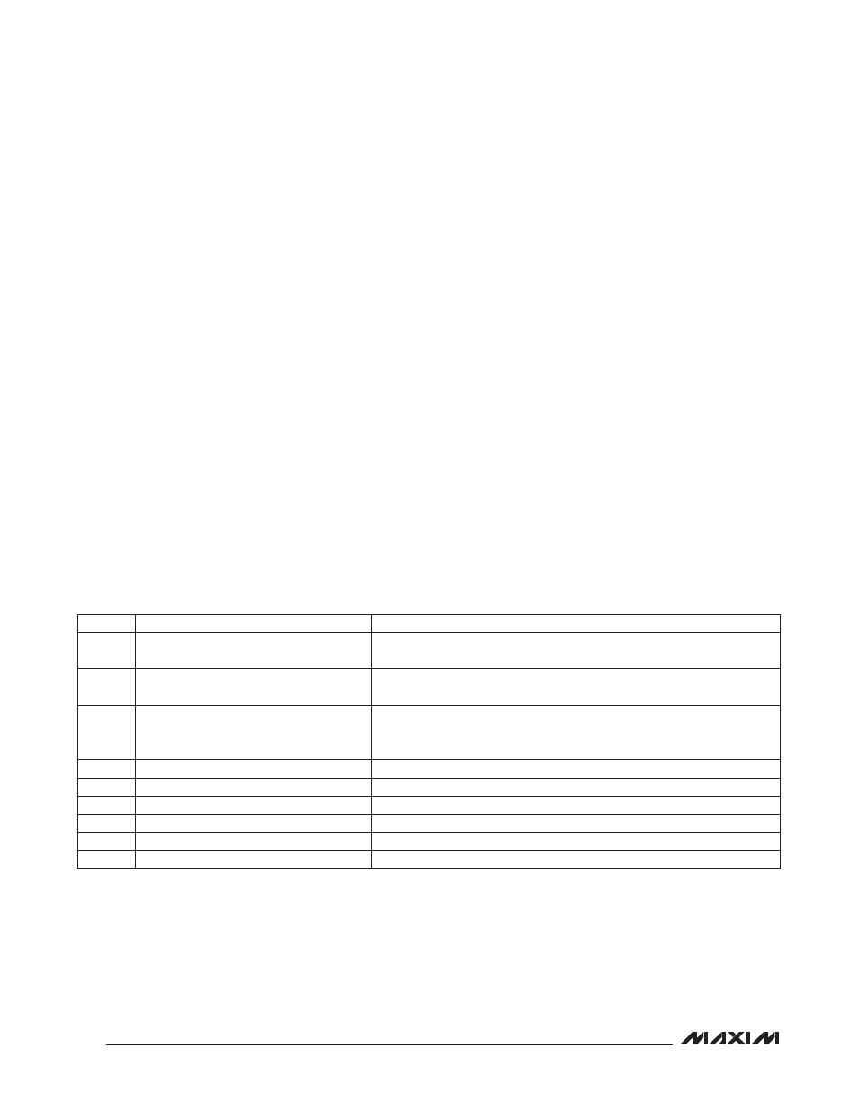
MFR_FAULT_RESPONSE (D9h)
The MFR_FAULT_RESPONSE command specifies the response to each fault condition supported by the device. In
response to a fault, the device always reports the fault in the appropriate status register and asserts the ALERT output
(if enabled in MFR_MODE). A CML fault cannot cause any device action other than setting the status bit and asserting
the ALERT output. The MFR_FAULT_RESPONSE command is described in Table 22.
Table 22. MFR_FAULT_RESPONSE
Note 1: All enabled temperature sensor faults are logically ORed together.
Note 2: Temperature faults affect all enabled power supplies. Supplies that are designated as global all respond in the same
manner. This response is the worst-case response of the global channels for the given fault. Supplies that are not global
respond to a temperature fault based upon the programmed response for the particular supply.
Note 3: The fault response for a power-supply fault is determined by MFR_FAULT_RESPONSE for the faulting channel. If this
channel is part of a global group, this fault response is performed for all the global channels.
BIT
BIT NAME
MEANING
15
NV_LOG
0 = Do not log the fault into MFR_NV_FAULT_LOG.
1 = Log the fault into MFR_NV_FAULT_LOG.
14
GLOBAL
0 = Affect only the selected page power supply.
1 = Affect all supplies with GLOBAL = 1.
13
UV_OV_FILTER
0 = Fault on first voltage sample excursion occurrence.
1 = Requires two consecutive voltage sample excursions before a fault is
declared and action is taken.
12:10
0
These bits always return a 0.
9:8
IOUT_OC_FAULT_LIMIT_RESPONSE[1:0] See Table 23.
7:6
OT_FAULT_LIMIT_RESPONSE[1:0]
See Table 23 (see Notes 1 and 2).
5:4
TON_MAX_FAULT_LIMIT_RESPONSE[1:0] See Table 23.
3:2
VOUT_UV_FAULT_LIMIT_RESPONSE[1:0] See Table 23.
1:0
VOUT_OV_FAULT_LIMIT_RESPONSE[1:0] See Table 23.