Temperature sensor operation, Table 6. ds75lv address pin configurations – Rainbow Electronics MAX34440 User Manual
Page 22
PMBus 6-Channel Power-Supply Manager
MAX34440
22
Temperature Sensor Operation
The device can monitor up to eight different temperature
sensors, seven external sensors plus its own internal
temperature sensor. The external temperature sensors
are all connected in parallel to the master I
2
C port
(MSDA and MSCL pins). The device can support up to
four DS75LV devices plus one MAX6695 device. Each
of the enabled temperature sensors is measured once
a second. The internal temperature sensor is averaged
four times to reduce the affect of noise. Each time the
device attempts to read a temperature sensor it checks
for faults. For the remote diode, a fault is defined as
either an open or short across the diode. For the internal
temperature sensor, a fault is defined as reading greater
than +130NC or less than -60NC. For the I
2
C temperature
sensors, a fault is defined as a communication access
failure. Temperature sensor faults are reported by set-
ting the temperature reading to 7FFFh. A temperature
sensor fault results in the setting of the TEMPERATURE
bit in STATUS_BYTE and STATUS_WORD and ALERT is
asserted (if enabled in MFR_MODE). No bits are set in
STATUS_MFR_SPECIFIC. Reading disabled tempera-
ture sensors returns a fixed value of 0000h.
The device can control up to four DS75LV digital temper-
ature sensors. The A0, A1, and A2 pins on the DS75LV
should be configured as shown in Table 6. The thermo-
stat function on the DS75LV is not used and thus the O.S.
output should be left open circuit.
The device can control one MAX6695, which consists of
one local temperature sensor and two remote diode tem-
perature sensors. Each of the temperature sensors can
be reinitialized by disabling and re-enabling the sensor
through MFR_TEMP_SENSOR_CONFIG. The valid range
for the MAX6695 temperature sensor is -40°C to +125°C.
The page assignment is shown in Table 6. The ALERT,
OT1, and OT2 pins on the MAX6695 are not used and
should be left open circuit.
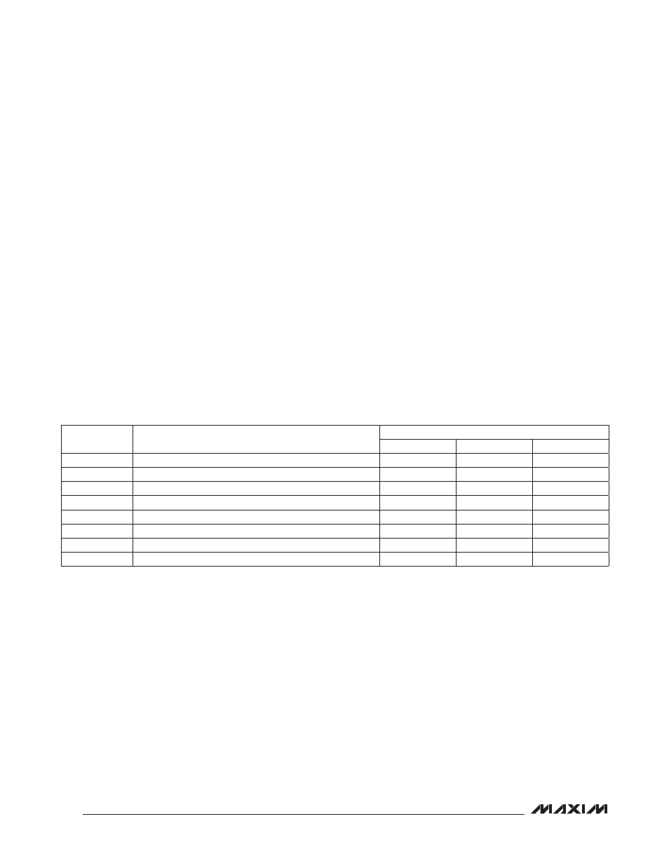
Table 6. DS75LV Address Pin Configurations
PAGE
MAX34440 I
2
C TEMP SENSOR
DS75LV ADDRESS PIN CONFIGURATION
A2
A1
A0
6
MAX34440 Internal
—
—
—
7
DS75LV (Address 0)
0
0
0
8
DS75LV (Address 1)
0
0
1
9
DS75LV (Address 2)
0
1
0
10
DS75LV (Address 3)
0
1
1
11
MAX6695 (Local Sensor)
—
—
—
12
MAX6695 (Remote Diode 1)
—
—
—
13
MAX6695 (Remote Diode 2)
—
—
—