Pin description (continued) – Rainbow Electronics MAX34440 User Manual
Page 11
PMBus 6-Channel Power-Supply Manager
MAX34440
11
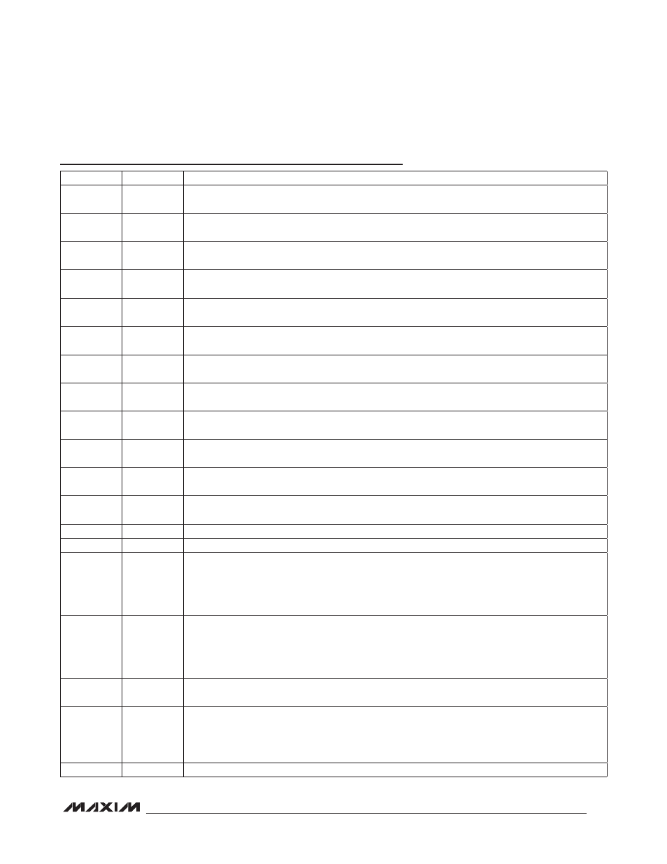
Pin Description (continued)
PIN
NAME
FUNCTION
18
PWM4
PWM Margin Output #4. High impedance when the margining is disabled. A 100% duty cycle implies
this pin is continuously high.
19
PSEN4
Power-Supply Enable Output #4. Programmable through MFR_MODE for either active high or active
low and either open drain or CMOS push-pull.
20
PWM3
PWM Margin Output #3. High impedance when the margining is disabled. A 100% duty cycle implies
this pin is continuously high.
22
REG18
Regulator for Low-Voltage Digital Circuitry. Bypass REG18 to V
SS
with 1FF and 10nF capacitors. Do
not connect other circuitry to this pin.
23
PSEN3
Power-Supply Enable Output #3. Programmable through MFR_MODE for either active high or active
low and either open drain or CMOS push-pull.
24
PWM2
PWM Margin Output #2. High impedance when the margining is disabled. A 100% duty cycle implies
this pin is continuously high.
25
PSEN2
Power-Supply Enable Output #2. Programmable through MFR_MODE for either active high or active
low and either open drain or CMOS push-pull.
26
PWM1
PWM Margin Output #1. High impedance when the margining is disabled. A 100% duty cycle implies
this pin is continuously high.
27
PSEN1
Power-Supply Enable Output #1. Programmable through MFR_MODE for either active high or active
low and either open drain or CMOS push-pull.
28
PWM0
PWM Margin Output #0. High impedance when the margining is disabled. A 100% duty cycle implies
this pin is continuously high.
29
REG25
Regulator for Analog Circuitry. Bypass REG25 to V
SS
with 1FF and 10nF capacitors. Do not connect
other circuitry to this pin.
30
PSEN0
Power-Supply Enable Output #0. Programmable through MFR_MODE for either active high or active
low and either open drain or CMOS push-pull.
31
SDA
I
2
C/SMBus-Compatible Input/Output
32
SCL
I
2
C/SMBus-Compatible Clock Input
33
A0/MUXSEL
SMBus Address 0 Input/Multiplexer Control Output. This dual-function pin is sampled on device
power-up to determine the SMBus address; connect a 100kI resistor from this pin to either V
SS
or
V
DD
to set the address. After device power-up, this pin becomes an output that acts as voltage/
current selector for an external analog multiplexer. MUXSEL is low for voltage measurements and
high for current measurements.
34
FAULT
Active-Low, Open-Drain Fault Input/Output. This pin is asserted when one or more of the power supplies
in a global group are shut down due to a fault condition. Also, this pin is monitored and, when it is
asserted, all power supplies in a global group are shut down. This pin is used to provide hardware
control for power supplies in a global group across multiple devices. This output is unconditionally
deasserted when RST is asserted or the device is power cycled. This pin has a 50Fs deglitch filter.
35
CONTROL
Device Enable. Option through ON_OFF_CONFIG for active-low or active-high power-supply control.
This pin has a 50Fs deglitch filter.
37
A1/PG
SMBus Address 1 Input/Power-Good Output. This dual-function pin is sampled on device power-up
to determine the SMBus address; connect a 100kI resistor from this pin to either V
SS
or V
DD
to set
the address. After device power-up, this pin becomes an output that transitions high when all the
enabled power supplies are above their associated POWER_GOOD_ON thresholds.
38
ALERT
Active-Low, Open-Drain Alert Output