Address select, Smbus/pmbus operation, Smbus/pmbus communication examples – Rainbow Electronics MAX34440 User Manual
Page 16: Address select smbus/pmbus operation, Table 2. pmbus/smbus serial-port address
PMBus 6-Channel Power-Supply Manager
MAX34440
16
Address Select
On device power-up, the device samples the A0 and A1
pins to determine the PMBus/SMBus serial-port address.
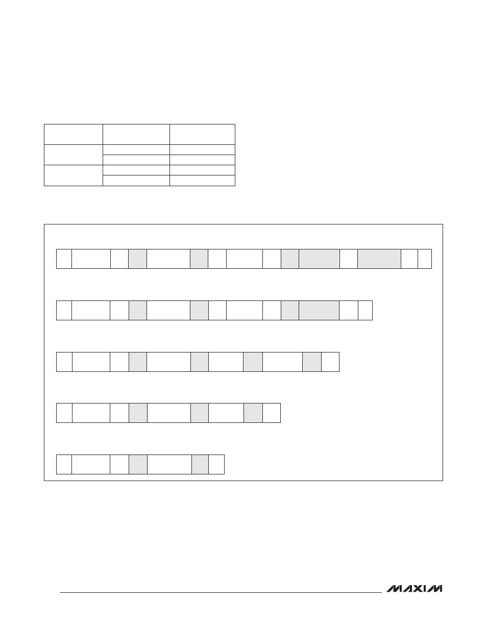
SMBus/PMBus Operation
The device implements the PMBus command structure
using the SMBus format. The structure of the data flow
between the host and the slave is shown below for sev-
eral different types of transactions. Data is sent most
significant bit (MSB) first.
Table 2. PMBus/SMBus Serial-Port Address
KEY:
S = START
Sr = REPEATED START
P = STOP
W = WRITE BIT (0)
R = READ BIT (1)
A = ACKNOWLEDGE (0)
NA = NOT ACKNOWLEDGE (1)
SHADED BLOCK = SLAVE TRANSACTION
SMBus/PMBus Communication Examples
A1
A0
7-BIT SLAVE
ADDRESS
100kI to V
SS
100kI to V
SS
1101 010 (D4h)
100kI to V
DD
1101 011 (D6h)
100kI to V
DD
100kI to V
SS
1101 100 (D8h)
100kI to V
DD
1101 101 (DAh)
READ WORD FORMAT
1
7
1
1
8
1
1
7
1
1
8
1
8
1
1
S
SLAVE
ADDRESS
W
A
COMMAND
CODE
A
Sr
SLAVE
ADDRESS
R
A
DATA BYTE
LOW
A
DATA BYTE
HIGH
NA
P
READ BYTE FORMAT
1
7
1
1
8
1
1
7
1
1
8
1
1
S
SLAVE
ADDRESS
W
A
COMMAND
CODE
A
Sr
SLAVE
ADDRESS
R
A
DATA BYTE
NA
P
WRITE WORD FORMAT
1
7
1
1
8
1
8
1
8
1
1
S
SLAVE
ADDRESS
W
A
COMMAND
CODE
A
DATA BYTE
LOW
A
DATA BYTE
HIGH
A
P
WRITE BYTE FORMAT
1
7
1
1
8
1
8
1
1
S
SLAVE
ADDRESS
W
A
COMMAND
CODE
A DATA BYTE
A
P
SEND BYTE FORMAT
1
7
1
1
8
1
1
S
SLAVE
ADDRESS
W
A
COMMAND
CODE
A
P