Max8730 low-cost battery charger, Applications information – Rainbow Electronics MAX8730 User Manual
Page 26
MAX8730
Low-Cost Battery Charger
26
______________________________________________________________________________________
Output Capacitor Selection
The output capacitor absorbs the inductor ripple cur-
rent and must tolerate the surge current delivered from
the battery when it is initially plugged into the charger.
As such, both capacitance and ESR are important
parameters in specifying the output capacitor as a filter
and to ensure stability of the DC-DC converter (see the
Compensation section). Beyond the stability require-
ments, it is often sufficient to make sure that the output
capacitor’s ESR is much lower than the battery’s ESR.
Either tantalum or ceramic capacitors can be used on
the output. Ceramic devices are preferable because of
their good voltage ratings and resilience to surge cur-
rents. For a ceramic output capacitor, select the capac-
itance according to the following equation:
The output ripple requirement of a charger is typically
only constrained by the overvoltage protection circuitry
of the battery protector and the overvoltage protection
of the charger. For proper operation, ensure that the
ripple is smaller than the overvoltage protection thresh-
old of both the charger and the battery protector. If the
protector’s overvoltage protection is filtered, the battery
protector may not be a constraint.
Applications Information
Adapter Soft-Start
The adapter selection MOSFETs may be soft-started to
reduce adapter surge current upon adapter selection.
Figure 10 shows the adapter soft-start application using
Miller capacitance for optimum soft-start timing and
power dissipation.
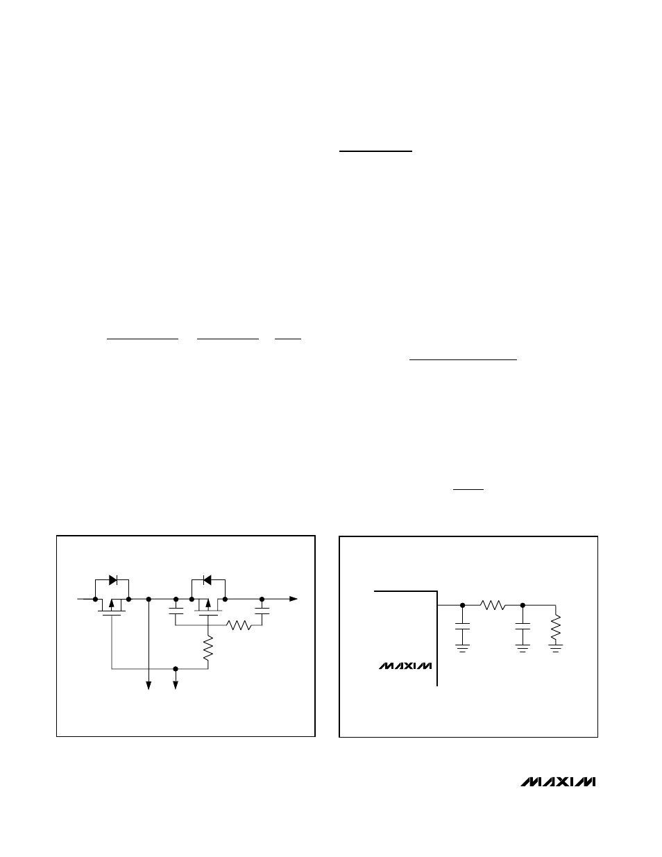
System Short-Circuit IINP Configuration
The MAX8730 has a system short-circuit protection fea-
ture. When V
IINP
is greater than 4.2V, the MAX8730
latches off PDS. PDS remains off until the adapter is
removed and reinserted. For fast response to system
overcurrent, add an RC (C13 and R15), as shown in
Figure 11.
Select R15 according to the following equation:
where:
V
SST
= 4.2V.
I
SST
= Short-circuit system current threshold. Since sys-
tem short-circuit triggers a latch, it is important to choose
I
SST
high enough to prevent unintentional triggers.
Select C13 according to the following equation:
C
t
R
Delay
13
15
=
R
V
G
x RS x I
x
R
SST
IINP
SST
15
1
0 7
10
=
−
.
C
k
x L x V
x
V
V
V
OUT
OFF
RIPPLE
SRC
BATT
BATT
>
−
+
2
8
1
1
ADAPTER
SYSTEM
LOAD
C
SS2
10nF
R
SS2
6k
Ω
R
SS1
18k
Ω
C
SS1
32nF
PDS
SRC
Figure
10. Adapter Soft-Start Modification
R10
C6
R15
MAX8730
C13
IINP
Figure
11. System Short-Circuit IINP Configuration