Max8730 low-cost battery charger – Rainbow Electronics MAX8730 User Manual
Page 20
MAX8730
Low-Cost Battery Charger
20
______________________________________________________________________________________
CCV, CCI, CCS, and LVC Control Blocks
The MAX8730 controls input current (CCS control loop),
charge current (CCI control loop), or charge voltage
(CCV control loop), depending on the operating condi-
tion. The three control loops—CCV, CCI, and CCS—are
brought together internally at the lowest voltage clamp
(LVC) amplifier. The output of the LVC amplifier is the
feedback control signal for the DC-DC controller. The
minimum voltage at the CCV, CCI, or CCS appears at
the output of the LVC amplifier and clamps the other
control loops to within 0.3V above the control point.
Clamping the other two control loops close to the low-
est control loop ensures fast transition with minimal
overshoot when switching between different control
loops (see the Compensation section).
Continuous-Conduction Mode
With sufficient charge current, the MAX8730’s inductor
current never crosses zero, which is defined as contin-
uous-conduction mode. The controller starts a new
cycle by turning on the high-side MOSFET. When the
charge-current feedback signal (CSI) is greater than
the control point (LVC), the CCMP comparator output
goes high and the controller initiates the off-time by
turning off the MOSFET. The operating frequency is
governed by the off-time, which depends upon V
BATT
.
At the end of the fixed off-time, the controller initiates a
new cycle only if the control point (LVC) is greater than
100mV, and the peak charge current is less than the
cycle-by-cycle current limit. Restated another way,
IMIN must be high, IMAX must be low, and OVP must
be low for the controller to initiate a new cycle. If the
peak inductor current exceeds the IMAX comparator
threshold or the output voltage exceeds the OVP
threshold, then the on-time is terminated. The cycle-by-
cycle current limit protects against overcurrent and
short-circuit faults.
The MAX8730 computes the off-time by measuring
V
BATT
:
t
OFF
= 5.6µs/V
BATT
for V
BATT
> 4V.
The switching frequency in continuous mode varies
according to the equation:
Discontinuous Conduction
The MAX8730 operates in discontinuous conduction
mode at light loads to make sure that the inductor cur-
rent is always positive. The MAX8730 enters discontinu-
ous conduction mode when the output of the LVC
control point falls below 100mV. For RS2 = 30m
Ω, this
corresponds to a peak inductor current of 222mA:
The MAX8730 implements slope compensation in dis-
continuous mode to eliminate multipulsing. This pre-
vents audible noise and minimizes the output ripple.
Compensation
The charge-voltage and charge current-regulation
loops are compensated separately and independently
at the CCV, CCI, and CCS pins.
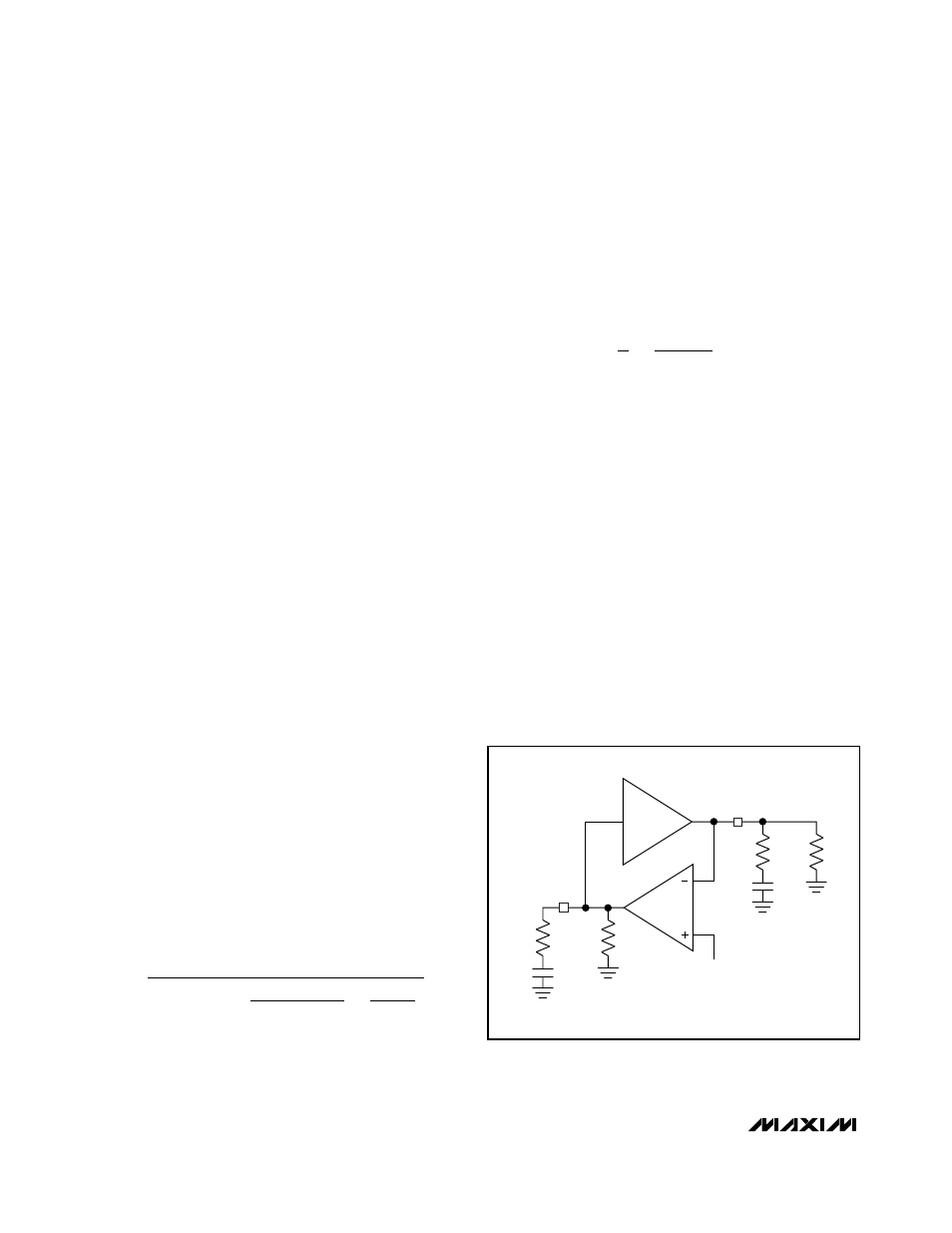
CCV Loop Compensation
The simplified schematic in Figure 4 is sufficient to
describe the operation of the MAX8730 when the volt-
age loop (CCV) is in control. The required compensa-
tion network is a pole-zero pair formed with C
CV
and
R
CV
. The pole is necessary to roll off the voltage loop’s
response at low frequency. The zero is necessary to
compensate the pole formed by the output capacitor
and the load. R
ESR
is the equivalent series resistance
(ESR) of the charger output capacitor (C
OUT
). R
L
is the
equivalent charger output load, where R
L
=
∆V
BATT
/
∆I
CHG
. The equivalent output impedance of the GMV
I
mV
RS
mA
DIS
=
Ч
Ч
=
1
2
100
15
2
111
f
V x
s x
V
V
V
SRC
BATT
BATT
.
=
−
+
1
5 6
1
1
µ
C
CV
C
OUT
R
CV
R
L
R
ESR
R
OGMV
CCV
BATT
GMV
REF
GM
OUT
Figure
4. CCV Loop Diagram