Max8730 low-cost battery charger, Dc-dc converter – Rainbow Electronics MAX8730 User Manual
Page 19
MAX8730
Low-Cost Battery Charger
______________________________________________________________________________________
19
reaches 100% depth of discharge, it is then recharged.
Connect MODE to GND to place the MAX8730 in
relearn mode. In relearn mode, charging stops, PDS
turns off, and PDL turns on.
To utilize relearn mode, there must be two source-con-
nected MOSFETs to prevent the AC adapter from sup-
plying current to the system through the P1’s body
diode. Connect SRC to the common source node of
two MOSFETs.
The system must alert the user before performing a
relearn cycle. If the user removes the battery during
relearn mode, the MAX8730 detects battery removal
and reconnects the AC adapter (PDS turns on and PDL
turns off). Battery removal is detected when the battery
falls below 5xRELTH.
LDO Regulator, REF, and SWREF
An integrated linear regulator (LDO) provides a 5.35V
supply derived from SRC, and delivers over 10mA of
load current. LDO biases the 4.2V reference (REF) and
most of the control circuitry. Bypass LDO to GND with a
1µF ceramic capacitor. An additional standalone 1%,
3.3V linear regulator (SWREF) provides 20mA and can
remain on when the adapter is absent. Set REFON low
to disable SWREF. Set REFON high for normal opera-
tion. SWREF must be enabled to allow charging.
Operating Conditions
• Adapter present: The adapter is considered to be
present when:
V
SRC
> 8V (max)
V
ASNS
> V
BATT
- 300mV (max)
• Charging: The MAX8730 allows charging when:
V
SRC
- V
CSIN
> 100mV (typ)
3 or 4 cells selected (MODE float or high condition)
ICTL > 110mV (max)
INPON is high
• Relearn mode: The MAX8730 enables relearn mode
when:
V
BATT
/ 5 > V
RELTH
MODE is grounded
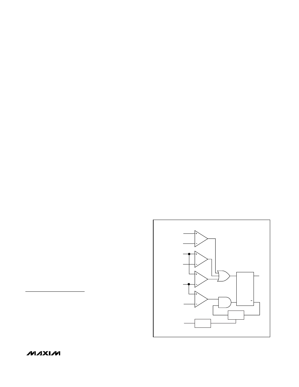
DC-DC Converter
The MAX8730 employs a step-down DC-DC converter
with a p-channel MOSFET switch and an external
Schottky diode. The MAX8730 features a constant-cur-
rent-ripple, current-mode control scheme with cycle-by-
cycle current limit. For light loads, the MAX8730
operates in discontinuous conduction mode for
improved efficiency. The operation of the DC-DC con-
troller is determined by the following four comparators
as shown in the functional block diagram in Figure 3:
• The IMIN comparator sets the peak inductor current
in discontinuous mode. IMIN compares the control
signal (LVC) against 100mV (corresponding to
222mA when RS2 = 30m
Ω). The comparator termi-
nates the switch on-time when IMIN exceeds the
threshold.
• The CCMP comparator is used for current-mode reg-
ulation in continuous conduction mode. CCMP com-
pares LVC against the charging-current feedback
signal (CSI). The comparator output is high and the
MOSFET on-time is terminated when the CSI voltage
is higher than LVC.
• The IMAX comparator provides a cycle-by-cycle cur-
rent limit. IMAX compares CSI to 2.95V (correspond-
ing to 6.56A when RS2 = 30m
Ω). The comparator
output is high and the MOSFET on-time is terminated
when the current-sense signal exceeds 6.56A. A new
cycle cannot start until the IMAX comparator output
goes low.
• The OVP comparator is used to prevent overvoltage
at the output due to battery removal. OVP compares
BATT against the set voltage; see the Setting Charge
Voltage section. When BATT is 20mV x CELLS above
the set value, OVP goes high and the MOSFET on-
time is terminated.
IMAX
CCMP
IMIN
OVP
CSI
2.95V
100mV
VCTL
SETPOINT
+ 20mV
BATT/CELLS
BATT
LVC
R
S
Q
Q
OFF-TIME
ONE-SHOT
OFF-TIME
COMPUTE
DH
DRIVER
Figure 3. DC-DC Converter Block Diagram