Max8730 low-cost battery charger, Table 2. ccv loop poles and zeros – Rainbow Electronics MAX8730 User Manual
Page 21
MAX8730
Low-Cost Battery Charger
______________________________________________________________________________________
21
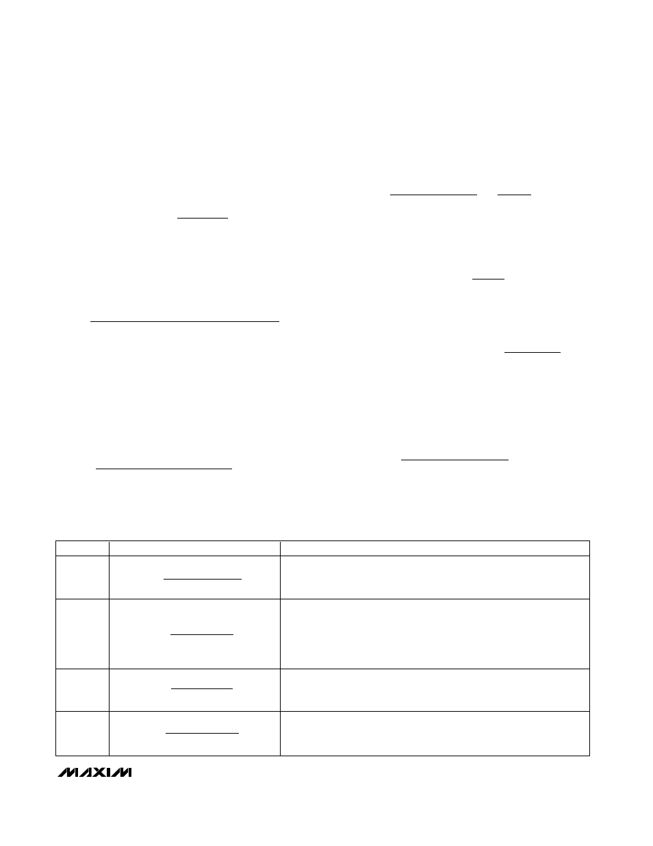
NAME
EQUATION
DESCRIPTION
CCV pole
Lowest frequency pole created by C
CV
and GMV’s finite output resistance.
Since R
OGMV
is very large and not well controlled, the exact value for the
pole frequency is also not well controlled (R
OGMV
> 10M
Ω).
CCV zero
Voltage-loop compensation zero. If this zero is at the same frequency or
lower than the output pole f
P_OUT
, then the loop-transfer function
approximates a single-pole response near the crossover frequency.
Choose C
CV
to place this zero at least 1 decade below crossover to ensure
adequate phase margin.
Output
pole
Output pole formed with the effective load resistance R
L
and output
capacitance C
OUT
. R
L
influences the DC gain but does not affect the
stability of the system or the crossover frequency.
Output
zero
Output ESR Zero. This zero can keep the loop from crossing unity gain if
f
Z_OUT
is less than the desired crossover frequency; therefore, choose a
capacitor with an ESR zero greater than the crossover frequency.
amplifier, R
OGMV
, is greater than 10M
Ω. The voltage
amplifier transconductance, GMV = 0.125µA/mV for 4
cells and 0.167µA/mV for 3 cells. The DC-DC converter
transconductance is dependent upon the charge cur-
rent-sense resistor RS2:
where A
CSI
= 15V/V and RS2 = 30m
Ω in the typical
application circuits, so GM
OUT
= 2.22A/V.
The loop transfer function is given by:
The poles and zeros of the voltage-loop transfer function
are listed from lowest frequency to highest frequency in
Table 2.
Near crossover, C
CV
is much lower impedance than
R
OGMV
. Since C
CV
is in parallel with R
OGMV,
C
CV
domi-
nates the parallel impedance near crossover. Additionally
R
CV
is much higher impedance than C
CV
and dominates
the series combination of R
CV
and C
CV
, so:
C
OUT
is typically much lower impedance than R
L
near
crossover so the parallel impedance is mostly capaci-
tive and:
If R
ESR
is small enough, its associated output zero has
a negligible effect near crossover and the loop-transfer
function can be simplified as follows:
Setting the LTF = 1 to solve for the unity-gain frequency
yields:
For stability, choose a crossover frequency lower than
1/5 the switching frequency. For example, choosing a
crossover frequency of 45kHz and solving for R
CV
using the component values listed in Figure 1 yields
R
CV
= 10k
Ω:
R
C
f
GMV GM
k
CV
OUT
CO CV
OUT
_
=
Ч
Ч
≅
Ч
2
10
π
Ω
f
GM
G
R
x C
CO CV
OUT
MV
CV
OUT
_
=
Ч
Ч
2
π
LTF
GM
R
sC
G
OUT
CV
OUT
MV
=
×
R
sC
R
sC
L
OUT
L
OUT
(
)
1
1
+
×
≅
R
sC
R
sC
R
R
OGMV x
CV
CV
CV
OGMV
CV
(
)
(
)
1
1
+
Ч
+
Ч
≅
LTF
GM
R
GMV
R
sC
R
sC
R
sC
R
sC
R
OUT
L
OGMV
OUT
ESR
CV
CV
CV
OGMV
OUT
L
(
)(
)
(
)(
)
=
Ч
Ч
Ч
Ч
+
Ч
+
Ч
+
Ч
+
Ч
1
1
1
1
GM
A
RS
OUT
CSI
=
×
1
2
Table 2. CCV Loop Poles and Zeros
f
R
C
P CV
OGMV
CV
_
=
×
1
2
π
f
R
C
Z CV
CV
CV
_
=
×
1
2
π
f
R
C
P OUT
L
OUT
_
=
×
1
2
π
f
R
C
Z OUT
ESR
OUT
_
=
×
1
2
π