Output pwm led drivers for message boards, Table 4. commands and data length, Table 5. global-intensity data bit justification – Rainbow Electronics MAX6973 User Manual
Page 14
MAX6972/MAX6973
Commands
The MAX6972/MAX6973 have four commands used to
load all operating mode and LED output current data.
Each command is uniquely identified by two bits, C1
and C0, embedded in the serial-interface protocol
structure. The commands Load CALDAC, Load Global-
Intensity PDM, and Load Configuration each require 16
bits of data (2 bytes) for every cascaded device. The
number of bits required for the command load individual
PWM varies by device and multiplex mode of operation.
Each cascaded device can receive unique data for
CALDACs, global intensity, configuration, and individual
PWM output drivers. Generally, all cascaded devices
are operated in the same configuration mode. The data
bytes are transmitted MSB first for all commands. The
commands are communicated to all cascaded devices
by the host using the synchronous serial-interface and
protocol structure (see the Serial Interface section for
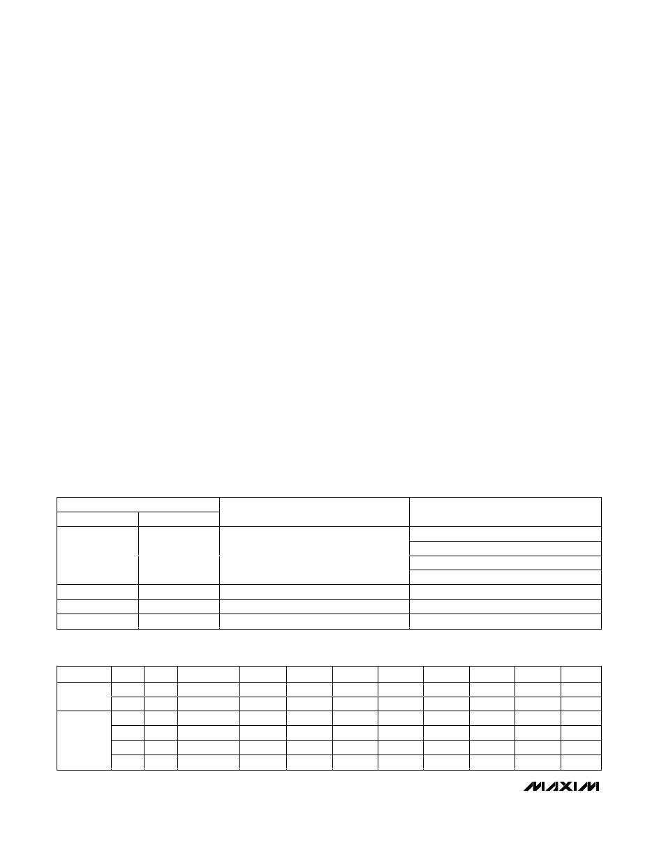
details). The four commands and the data lengths for
each command are shown in Table 4.
The MAX6972, operating in nonmultiplexed mode,
requires sixteen 12-bit individual PWM data (192 bits
total) and requires thirty-two 12-bit data (384 bits total)
in multiplexed operation mode. Similarly, the MAX6973
operating in nonmultiplexed mode requires sixteen 14-bit
individual-intensity PWM data (224 bits total) and
requires thirty-two 14-bit (448 bits total) data in multi-
plexed mode. The individual PWM data are loaded into
an intermediate latch and transferred to the actual
PWM latches at subframe 0 and PWM clock 0.
Both Y and Z calibration DACs are loaded with 8-bit
data each in nonmultiplexed and multiplexed modes.
Data is updated immediately into the CALDAC latches
(see Table 8).
The MAX6972/MAX6973 require one data byte to set the
global-intensity PDM for all output drivers. The global-
intensity PDM data has a variable number of active bits
depending on the multiplex operating mode and, for
the MAX6973, the global-quarter setting. The number of
bits used for global-intensity control is always justified
to the LSB of the data byte, as shown in Table 5. One
byte of data is sent twice with the global-intensity PDM
data bits justified to the LSB. Data is updated into the
PWM latches at subframe 0 and PWM clock 0 (see
Table 9).
When using the MAX6973 5-bit global-intensity setting,
the settings range from 0 to 63 to set the global intensity
from 1 to 64 subframes ON to 64 out of 64 subframes ON.
When using the MAX6972 7-bit global-intensity setting,
the settings range from 0 to 127 to set the global inten-
sity from 1 out of 128 subframes ON to 128 out of 128
subframes ON.
16-Output PWM LED Drivers
for Message Boards
14
______________________________________________________________________________________
CMD[1:0]
C1
C0
COMMAND
DATA LENGTH PER CASCADED DEVICE
192 bits (MAX6972 nonmultiplexed)
384 bits (MAX6972 multiplexed)
224 bits (MAX6973 nonmultiplexed)
0
0
Load individual PWM
448 bits (MAX6973 multiplexed)
0
1
Load CALDAC
16 bits
1
0
Load global-intensity PDM
16 bits
1
1
Load configuration
16 bits
Table 4. Commands and Data Length
PART
GLB4
MUX
TOTAL BITS
MSB D7
D6
D5
D4
D3
D2
D1
LSB D0
X
0
7
0
Bit[6]
Bit[5]
Bit[4]
Bit[3]
Bit[2]
Bit[1]
Bit[0]
MAX6972
X
1
6
0
0
Bit[5]
Bit[4]
Bit[3]
Bit[2]
Bit[1]
Bit[0]
0
0
5
0
0
0
Bit[4]
Bit[3]
Bit[2]
Bit[1]
Bit[0]
0
1
4
0
0
0
0
Bit[3]
Bit[2]
Bit[1]
Bit[0]
1
0
3
0
0
0
0
0
Bit[2]
Bit[1]
Bit[0]
MAX6973
1
1
2
0
0
0
0
0
0
Bit[1]
Bit[0]
Table 5. Global-Intensity Data Bit Justification