Table 3. transmit truth table ( oe = 0), Table 4a. receive truth table ( oe = 1), Table 4b. receive truth table ( oe = 1, sus = 1) – Rainbow Electronics MAX13483E User Manual
Page 9
Sharing Mode
Connect V
L
to a system power supply and leave V
BUS
(or V
BUS
and V
TRM
) unconnected or connect to GND.
D+ and D- enter a tri-state mode, allowing other circuitry
to share the USB D+ and D- lines. V
L
consumes less
than 20µA of supply current. D+ and D- withstand exter-
nal signals up to +5.5V in sharing mode (Table 2).
Device Control
OE
OE controls the direction of communication. Drive OE
low to transfer data from the logic side to the USB side.
For
OE = low, VP and VM serve as differential driver
inputs to the USB transmitter. Drive
OE high to transfer
data from the USB side to the logic side. For
OE = high,
VP and VM serve as single-ended receiver outputs
from the USB inputs (D+ and D-). RCV serves as a dif-
ferential receiver output, regardless of the state of
OE.
ENUM
(MAX13481E/MAX13482E)
The MAX13481E/MAX13482E feature an active-low enu-
merate function that allows software control of the 1.5k
Ω
pullup resistor and switch to D+ for full-speed operation.
For the MAX13481E, connect a 1.5k
Ω pullup resistor
between D+ and VPU. The MAX13481E provides an
internal switch that pulls VPU to a +3.3V voltage. Drive
ENUM high to disconnect VPU from voltage. Drive
ENUM low to connect VPU and the external pullup resis-
tor to the +3.3V voltage.
The MAX13482E has an internal 1.5k
Ω resistor that
connects at VPUR. Connect VPUR directly to D+. Drive
ENUM high to disconnect the internal pullup resistor at
VPUR. Drive
ENUM low to connect the internal pullup
resistor to VPUR.
SUS
The SUS state determines whether the MAX13481E/
MAX13482E/MAX13483E operate in normal mode or in
suspend mode. Connect SUS to GND to enable normal
operation. Drive SUS high to enable suspend mode.
RCV asserts low and VP and VM remain active in sus-
pend mode (Tables 3 and 4). In suspend mode, supply
current is reduced.
MAX13481E/MAX13482E/MAX13483E
±15kV ESD-Protected USB Transceivers with
External/Internal Pullup Resistors
_______________________________________________________________________________________
9
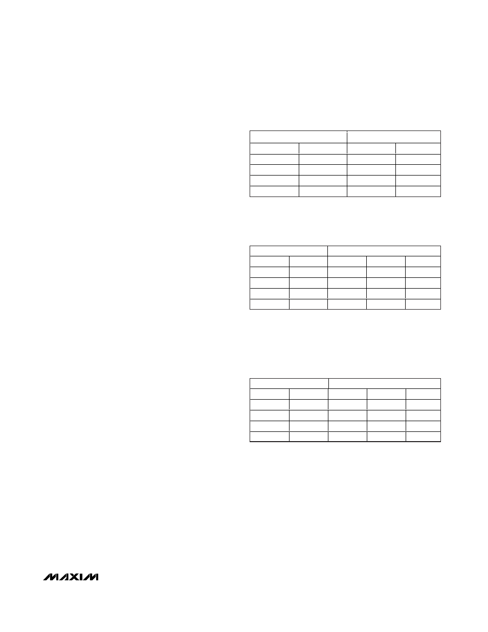
INPUTS
OUTPUTS
VP
VM
D+
D-
0
0
0
0
0
1
0
1
1
0
1
0
1
1
1
1
Table 3. Transmit Truth Table
(
OE = 0)
INPUTS
OUTPUTS
D+
D-
VP
VM
RCV
0
0
0
0
RCV*
0
1
0
1
0
1
0
1
0
1
1
1
1
1
X
Table 4a. Receive Truth Table
(
OE = 1)
INPUTS
OUTPUTS
D+
D-
VP
VM
RCV
0
0
0
0
0
0
1
0
1
0
1
0
1
0
0
1
1
1
1
0
Table 4b. Receive Truth Table
(
OE = 1, SUS = 1)
* = Last state
X = Undefined