Pin description (continued) – Rainbow Electronics MAX13483E User Manual
Page 7
MAX13481E/MAX13482E/MAX13483E
±15kV ESD-Protected USB Transceivers with
External/Internal Pullup Resistors
_______________________________________________________________________________________
7
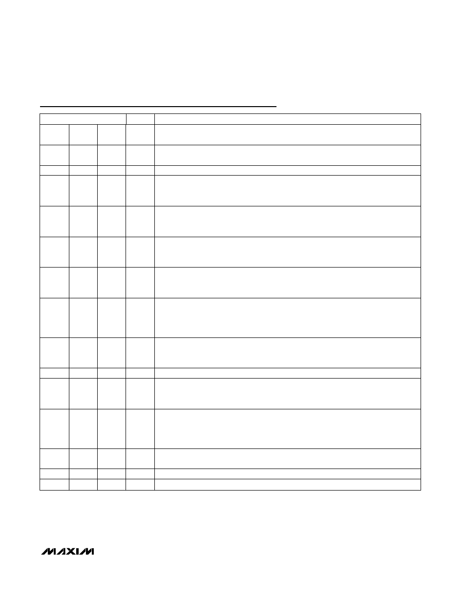
Pin Description (continued)
PIN
NAME
FUNCTION
4
4
4
VM
Receiver Output/Driver Input. VM functions as a receiver output when
OE = V
L
. VM
duplicates D- when receiving. VM functions as a driver input when
OE = GND.
5
5
—
ENUM
Active-Low Enumerator-Function-Selection Input.
ENUM controls the pullup resistor or
switch connection. See the
ENUM section.
6
6
6
GND
Ground
7
7
7
SUS
Suspend Input. Drive SUS low for normal operation. Drive SUS high for low-power state.
RCV asserts low and D+/ D- are high impedance in suspend mode. VP and VM remain
active in suspend mode.
9
9
9
OE
Output Enable. Drive
OE to GND to enable the D+/D- transmitter outputs. Drive OE to V
L
to
disable the transmitter outputs.
OE also controls the I/O directions of VP and VM (see
Tables 3 and 4).
10
10
10
D-
USB Input/Output. For
OE = GND, D- functions as a USB output with VM providing the input
signal. For
OE = V
L
, D- functions as a USB input with VM functioning as a single-ended
receiver output.
11
11
11
D+
USB Input/Output. For
OE = GND, D+ functions as a USB output with VP providing the
input signal. For
OE = V
L
, D+ functions as a USB input with VP functioning as a single-
ended receiver output.
12
12
12
V
TRM
Regulated Output Voltage. V
TRM
provides a 3.3V output derived from V
BUS
. Bypass V
TRM
to GND with a 1µF (min) low-ESR capacitor such as ceramic or plastic film types. V
TRM
provides power to internal circuitry, the internal D+ pullup resistor, VPU and VPUR. Do not
use V
TRM
to power external circuitry.
13
—
—
VPU
Pullup Voltage. For
ENUM = GND, VPU is pulled to an internal 3.3V voltage. Connect a
1.5k
Ω resistor between D+ and VPU for full-speed operation. For ENUM = V
L
, VPU is high
impedance.
—
—
13
I.C.
Internally Connected. Leave open. Do not connect to external circuitry.
—
13
—
VPUR
Internal Pullup Resistor. VPUR is pulled to an internal 3.3V voltage through a 1.5k
Ω resistor
(
ENUM = GND). Connect VPUR to D+ for full-speed operation. For ENUM = V
L
, VPU is
high impedance.
14
14
14
V
BUS
USB-Side Power-Supply Input. Connect a +4V to +5.5V power supply to V
BUS
. V
BUS
supplies power to the internal regulator. Bypass V
BUS
to GND with a 1µF ceramic
capacitor. Connect V
BUS
and V
TRM
together when powering the MAX13481E/MAX13482E/
MAX13483E with an external power supply.
15
15
15
V
L
Digital Input/Output Connection Logic Supply. Connect a +1.6V to +3.6V supply to V
L
.
Bypass V
L
to GND with a 0.1µF (min) low-ESR ceramic capacitor.
—
16
16
BD
USB Detector Output (Push/Pull). A high at BD signals to the ASIC that V
BUS
is present.
EP
EP
EP
EP
Exposed Paddle. Connect EP to GND.