Timing diagrams, Machine model – Rainbow Electronics MAX13483E User Manual
Page 11
stand voltage measured to IEC 61000-4-2 generally is
lower than that measured using the Human Body
Model. Figure 8 shows the IEC 61000-4-2 model. The
Contact Discharge method connects the probe to the
device before the probe is charged.
Machine Model
The Machine Model for ESD tests all connections using
a 200pF storage capacitor and zero discharge resis-
tance. Its objective is to emulate the stress caused by
contact that occurs with handling and assembly during
manufacturing. All pins require this protection during
manufacturing, not just inputs and outputs. After PC
board assembly, the Machine Model is less relevant to
I/O ports.
MAX13481E/MAX13482E/MAX13483E
±15kV ESD-Protected USB Transceivers with
External/Internal Pullup Resistors
______________________________________________________________________________________
11
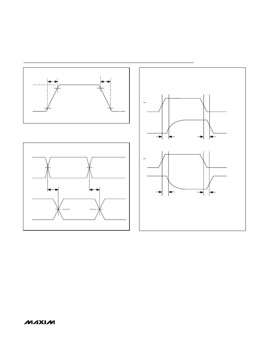
V
OHD
V
OLD
90%
10%
90%
10%
t
FR
, t
LR
t
FF
, t
LF
Figure 1. Rise and Fall Times
VM
VP
D-
D+
t
PLH_DRV
t
PHL_DRV
V
CRS_F
, V
CRS_L
VP AND VM RISE/FALL TIMES < 4ns
Figure 2. Timing of VP and VM to D+ and D-
OE
D+/D-
t
PLZ_DRV
t
PZL_DRV
t
PHZ_DRV
t
PZH_DRV
VP/VM
CONNECTED TO GND,
D+/D- CONNECTED
TO PULLUP
VP/VM
CONNECTED TO V
L
,
D+/D- CONNECTED
TO PULLDOWN
OE
D+/D-
Figure 3. Driver’s Enable and Disable Timing
Timing Diagrams