Rainbow Electronics MAX13483E User Manual
Page 6
MAX13481E/MAX13482E/MAX13483E
±15kV ESD-Protected USB Transceivers with
External/Internal Pullup Resistors
6
_______________________________________________________________________________________
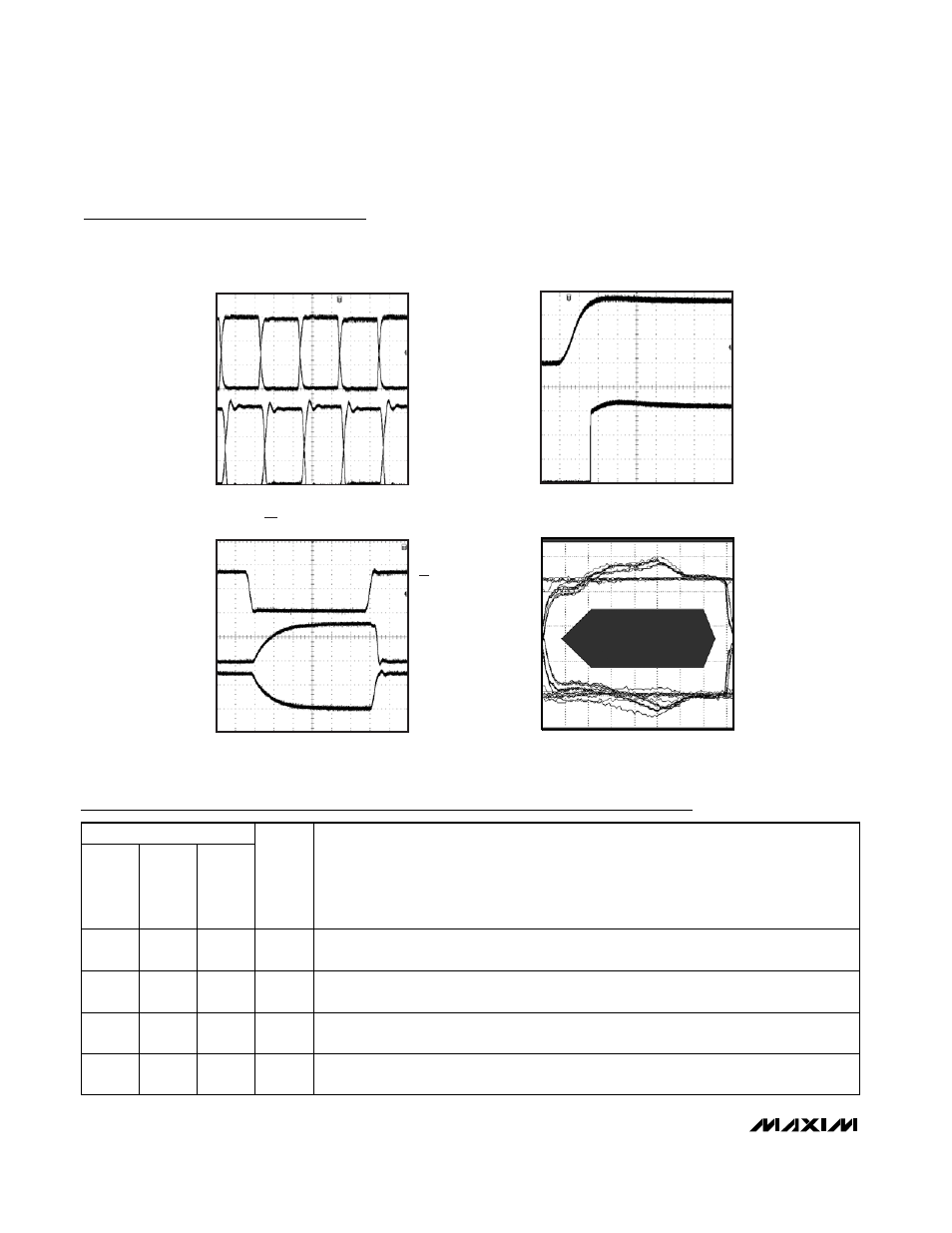
OE, VP, VM TIMING
MAX13481E toc15
20ns/div
VM
2V/div
OE
2V/div
VP
2V/div
EYE DIAGRAM
MAX13481E toc16
4
-1
2
1
0
3
0
10
20
30
40
50
60
70
80
TIME (ns)
D+ AND D- (V)
Pin Description
Typical Operating Characteristics (continued)
(V
BUS
= 5V, V
L
= +3.3V, T
A
= +25°C, unless otherwise noted.)
TRANSMISSION IN
SUSPEND MODE
MAX13481E toc13
VP
D-
D+
VM
20ns/div
1V/div
1V/div
BUS DETECT RESPONSE
MAX13481E toc14
1
μs/div
BD
1V/div
V
BUS
2V/div
PIN
MAX13481E
MAX13482E
MAX13483E
NAME
FUNCTION
8, 16
1, 8
1, 5,
8
N.C.
No Connection. Not internally connected.
1
—
—
SP
Connect to V
L
for Pin Compatibility to the MIC2551A or Leave Floating. Not internally
connected.
2
2
2
RCV
Differential Receiver Output. RCV responds to the differential input on D+ and D-. RCV
asserts low when SUS = V
L.
3
3
3
VP
Receiver Output/Driver Input. VP functions as a receiver output when
OE = V
L
. VP
duplicates D+ when receiving. VP functions as a driver input when
OE = GND.