Detailed description, Applications information, Table 1. power-supply configuration – Rainbow Electronics MAX13483E User Manual
Page 8: Table 2. disable-mode and sharing-mode connection
MAX13481E/MAX13482E/MAX13483E
±15kV ESD-Protected USB Transceivers with
External/Internal Pullup Resistors
8
_______________________________________________________________________________________
Detailed Description
The MAX13481E/MAX13482E/MAX13483E ±15kV ESD-
protected USB-compliant transceivers convert single-
ended or differential logic-level signals to USB signals,
and USB signals to single-ended or differential logic
signals. These devices fully comply to USB 2.0 when
operating at full-speed (12Mbps), and operate with V
L
as low as 1.6V, ensuring compatibility with low-voltage
ASICs. Integrated ±15kV ESD-circuitry protection pro-
tects D+ and D- bus connections.
The MAX13481E/MAX13483E require an external 1.5k
Ω
pullup resistor to V
TRM
for full-speed operation. The
MAX13481E requires an external 1.5k
Ω pullup resistor
and feature an active-low enumeration function that
connects a +3.3V voltage at VPU. The MAX13482E fea-
tures an active-low enumeration function that connects
a 1.5k
Ω pullup resistor at VPUR for full-speed opera-
tion. The MAX13482E/MAX13483E also provide a bus
detect (BD) output that asserts high when V
BUS
> 3.6V.
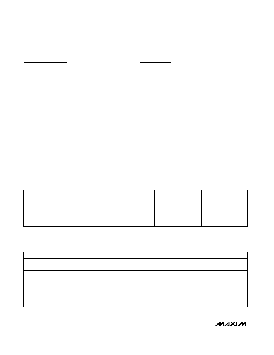
Applications Information
Power-Supply Configurations
Normal Operating Mode
Connect V
L
and V
BUS
to system power supplies (Table 1).
Connect V
L
to a +1.6V to +3.6V supply. Connect V
BUS
to a +4.0V to +5.5V supply or to the V
BUS
connector.
Alternatively, these parts can derive power from a sin-
gle Li+ cell. Connect the battery to V
BUS
. V
TRM
remains
above +3.0V for V
BUS
as low as +3.1V. Additionally, the
devices can be powered by an external +3.3V ±10%
voltage regulator. Connect V
BUS
and V
TRM
to an exter-
nal +3.3V voltage regulator. V
BUS
no longer consumes
current to power the internal linear regulator in this con-
figuration. The bus detect function (BD) on the
MAX13482E and MAX13483E does not function when
the device is powered this way.
Disable Mode
Connect V
BUS
to a system power supply and leave V
L
unconnected or connect to GND. D+ and D- enter a tri-
state mode and V
BUS
(or V
BUS
and V
TRM
) consumes
less than 20µA of supply current. D+ and D- withstand
external signals up to +5.5V in disable mode (Table 2).
V
BUS
(V)
V
TRM
(V)
V
L
(V)
CONFIGURATION
NOTES
+4.0 to +5.5
+3.0 to +3.6 output
+1.6 to +3.6
Normal mode
—
+4.0 to +5.5
+3.0 to +3.6 output
GND or floating
Disable mode
Table 2
GND or floating
High Z
+1.6 to +3.6
Sharing mode
Table 2
+3.1 to +4.5
+3.0 to +3.6 output
+1.6 to +3.6
Battery supply
+3.0 to +3.6
+3.0 to +3.6 input
+1.6 to +3.6
Voltage regulator supply
—
Table 1. Power-Supply Configuration
INPUTS/OUTPUTS
DISABLE MODE
SHARING MODE
V
BUS
/ V
TRM
4V to 5.5V
Floating or connected to GND
V
L
Floating or connected to GND
1.6V to 3.6V input
D+ and D-
High impedance
High impedance
For
OE = low, high impedance
VP and VM
Invalid*
For
OE = high, output logic high
RCV
Invalid*
Undefined
BD
(MAX13482E/MAX13483E)
Invalid*
Low
Table 2. Disable-Mode and Sharing-Mode Connection
*High impedance or logic low