Mfr_mode (d1h), Table 26. mfr_mode – Rainbow Electronics MAX34441 User Manual
Page 39
PMBus 5-Channel Power-Supply Manager
and Intelligent Fan Controller
MAX34441
39
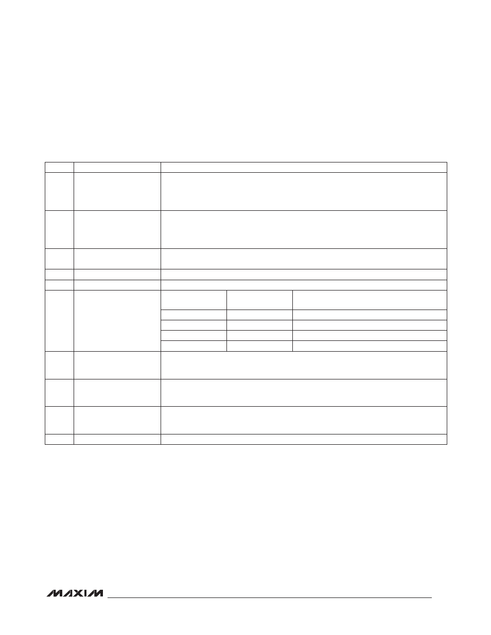
MFR_MODE (D1h)
The MFR_MODE command is used to configure the device to support manufacturer specific commands. The MFR_
MODE command is described in Table 26.
Table 26. MFR_MODE
Note: If a dual tachometer fan is used, it is recommended that the slower tachometer signal be presented to the TACH pin when
TACHSEL = 0.
BIT
BIT NAME
MEANING
15
FORCE_NV_FAULT_LOG
Setting this bit to 1 forces the device to log data into the nonvolatile fault log. Once set, the
device clears this bit when the action is completed. The host must set again for subsequent
action. If an error occurs during this action, the device sets the CML bit in STATUS_BYTE
and STATUS_WORD; no bits are set in STATUS_CML.
14
CLEAR_NV_FAULT_LOG
Setting this bit to 1 forces the device to clear the nonvolatile fault log by writing FFh to all
byte locations. Once set, the device clears this bit when the action is completed. The host
must set again for subsequent action. If an error occurs during this action, the device sets
the CML bit in STATUS_BYTE and STATUS_WORD; no bits are set in STATUS_CML.
13
ALERT
0 = ALERT disabled (device does not respond to ARA).
1 = ALERT enabled (device responds to ARA and ARA must be used).
12
0
This bit always returns a 0.
11
SOFT_RESET
This bit must be set, then cleared and set again within 8ms for a soft reset to occur.
10:9
PGTIME[1:0]
PGTIME1
PGTIME0
TIME FROM POWER GOOD DETERMINED
UNTIL PG OUTPUT IS ASSERTED (ms)
0
0
Immediately
0
1
100
1
0
500
1
1
1000
8
PG_SELECT
0 = PG/TACHSEL output is power-good indication.
1 = PG/TACHSEL output is TACHSEL (for dual tachometer fans). For dual tachometer fans,
this output is toggled every 500ms.
7
PSEN_PP_OD
Applies to all PSEN outputs.
0 = PSEN push-pull output.
1 = PSEN open-drain output.
6
PSEN_HI_LO
Applies to all PSEN outputs.
0 = PSEN active low.
1 = PSEN active high.
5:0
0
These bits always return a 0.