Fan_config_1_2 (3ah), Fan_command_1 (3bh), Fan_config_1_2 (3ah) fan_command_1 (3bh) – Rainbow Electronics MAX34441 User Manual
Page 31
PMBus 5-Channel Power-Supply Manager
and Intelligent Fan Controller
MAX34441
31
FAN_CONFIG_1_2 (3Ah)
The FAN_CONFIG_1_2 command is used in conjunction with MFR_FAN_CONFIG to configure the fan. See the
MFR_FAN_CONFIG (F1h) section for more details on this command. The FAN_CONFIG_1_2 command is described
in Table 15.
FAN_COMMAND_1 (3Bh)
The FAN_COMMAND_1 command is used to override the device’s automatic fan-control function and force the fan
to either a fixed PWM duty-cycle value or a target fan speed (in RPM). The units of the FAN_COMMAND_1 are either
percent duty cycle (if bit 6 of FAN_CONFIG_1_2 is zero) or RPM (if bit 6 of FAN_CONFIG_1_2 is one). Any value less
than 0% duty cycle or 0 RPM causes the device to ignore this command and use the automatic fan-control function.
Any value greater than or equal to 0% duty cycle or 0 RPM causes the device to ignore the automatic fan-control func-
tion and force the fan to the PWM value or RPM value provided by the FAN_COMMAND_1 command. The 2 data bytes
are in DIRECT format.
Table 16. PWM Fan Mode (FAN_CONFIG_1_2 Bit 6 = 0)
Table 17. RPM Fan Mode (FAN_CONFIG_1_2 Bit 6 = 1)
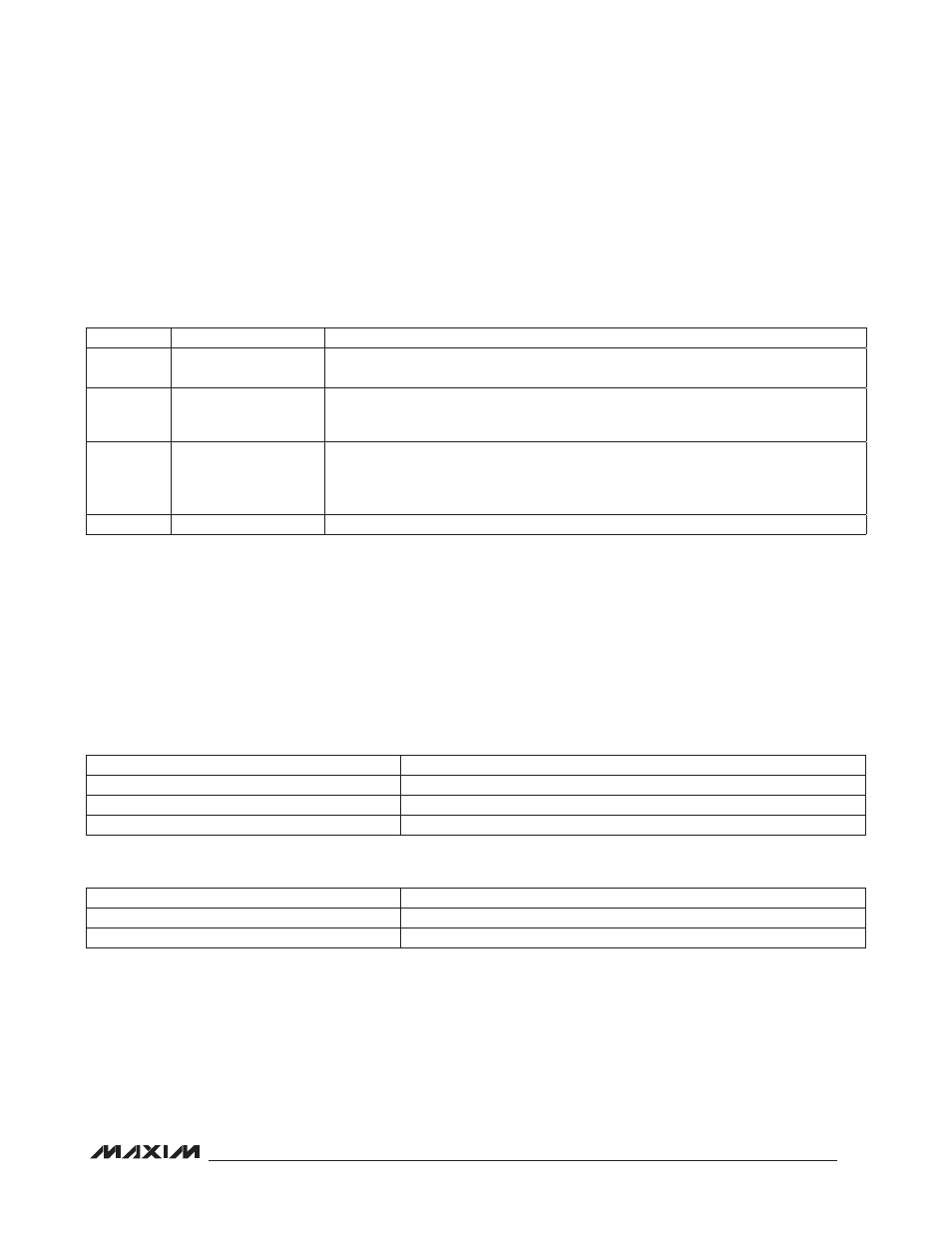
Table 15. FAN_CONFIG_1_2 Command Byte
FAN_COMMAND_1 VALUE
DEVICE RESPONSE
8000h to FFFFh
Ignore FAN_COMMAND_1 and use automatic fan-control function
0000h to 2710Fh
0 to 100% fan PWM duty cycle
2711h to 7FFFh
100% fan PWM duty cycle
FAN_COMMAND_1 VALUE
DEVICE RESPONSE
8000h to FFFFh
Ignore FAN_COMMAND_1 and use automatic fan-control function
0000h to 7FFFh
0 to 32,767 RPM
BIT
NAME
MEANING
7
FAN ENABLE
0 = Fan disabled (PWM5 forced low).
1 = Fan enabled.
6
RPM/PWM
0 = PWM duty cycle is the fan-controlling
parameter.
1 = RPM is the fan-controlling parameter.
5:4
PULSE
00 = 1 Tach pulse per fan revolution.
01 = 2 Tach pulses per fan revolution.
10 = 3 Tach pulses per fan revolution.
11 = 4 Tach pulses per fan revolution.
3:0
0
These bits always return a 0.