Detailed description, Table 1. pmbus command codes – Rainbow Electronics MAX34441 User Manual
Page 14
PMBus 5-Channel Power-Supply Manager
and Intelligent Fan Controller
MAX34441
14
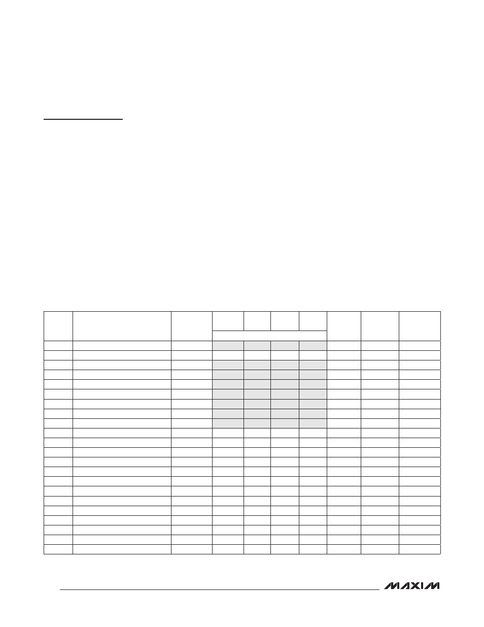
Table 1. PMBus Command Codes
Detailed Description
The MAX34441 is a highly integrated system monitor
based upon a 4MHz, 16-bit, MAXQ
M
microcontroller with
factory-programmed functionality to monitor up to five
power supplies and a system cooling fan. The device
provides power-supply closed-loop control, fan-speed
monitoring, and local/remote thermal-sensing facilities.
The power-supply manager monitors the power-supply
output voltage and constantly checks for user-pro-
grammable overvoltage and undervoltage thresholds. It
also can margin the power-supply output voltage up or
down by a user-programmable level. The margining is
performed in a closed-loop arrangement, whereby the
device automatically adjusts a pulse-width-modulated
(PWM) output and then measures the resultant output
voltage. The power-supply manager can also sequence
the supplies in any order at both power-up and power-
down. With the addition of an external current-sense
amplifier, the device can also monitor currents.
Thermal monitoring can be accomplished using up to six
temperature sensors, including an on-chip thermal sen-
sor, four DS75LV digital thermometers, and a remote ther-
mal diode. Temperature offset can be added to individual
sensors to compensate for thermal differences in a sys-
tem. Communication with the DS75LV temperature sensor
is conducted through a dedicated I
2
C/SMBus interface.
The device also contains closed-loop fan-speed control.
Based on user-programmable settings for fan-control
PWM duty cycles or for fan RPM speeds at particu-
lar temperature breakpoints, the device automatically
adjusts the fan speed in a manner to reduce audible
noise and power consumption.
The device provides ALERT and FAULT output signals.
Host communications are conducted through a PMBus-
compatible communications port. Address input con-
nections are also provided to allow up to four MAX34441
devices to reside on the system’s I/O bus.
MAXQ is a registered trademark of Maxim Integrated
Products, Inc.
CODE
COMMAND NAME
TYPE
PAGE
0–4
PAGE
5
PAGE
6–11
PAGE
255
NO. OF
BYTES
FLASH
STORED
(NOTE 2)
DEFAULT
VALUE
(NOTE 2)
(NOTE 1)
00h
PAGE
R/W Byte
R/W
R/W
R/W
R/W
1
N
00h
01h
OPERATION
R/W Byte
R/W
—
—
W
1
N
00h
02h
ON_OFF_CONFIG
R/W Byte
R/W
R/W
R/W
R/W
1
Y
1Ah
03h
CLEAR_FAULTS
Send Byte
W
W
W
W
0
N
—
10h
WRITE_PROTECT
R/W Byte
R/W
R/W
R/W
R/W
1
N
00h
11h
STORE_DEFAULT_ALL
Send Byte
W
W
W
W
0
N
—
12h
RESTORE_DEFAULT_ALL
Send Byte
W
W
W
W
0
N
—
19h
CAPABILITY
Read Byte
R
R
R
R
1
N
00h/10h
20h
VOUT_MODE
Read Byte
R
R
R
R
1
FIXED
40h
25h
VOUT_MARGIN_HIGH
R/W Word
R/W
—
—
—
2
Y
0000h
26h
VOUT_MARGIN_LOW
R/W Word
R/W
—
—
—
2
Y
0000h
2Ah
VOUT_SCALE_MONITOR
R/W Word
R/W
—
—
—
2
Y
7FFFh
38h
IOUT_CAL_GAIN
R/W Word
R/W
—
—
—
2
Y
0000h
3Ah
FAN_CONFIG_1_2
R/W Byte
—
R/W
—
—
1
Y
00h
3Bh
FAN_COMMAND_1
R/W Word
—
R/W
—
—
2
Y
FFFFh
40h
VOUT_OV_FAULT_LIMIT
R/W Word
R/W
—
—
—
2
Y
7FFFh
42h
VOUT_OV_WARN_LIMIT
R/W Word
R/W
—
—
—
2
Y
7FFFh
43h
VOUT_UV_WARN_LIMIT
R/W Word
R/W
—
—
—
2
Y
0000h
44h
VOUT_UV_FAULT_LIMIT
R/W Word
R/W
—
—
—
2
Y
0000h
46h
IOUT_OC_WARN_LIMIT
R/W Word
R/W
—
—
—
2
Y
7FFFh
4Ah
IOUT_OC_FAULT_LIMIT
R/W Word
R/W
—
—
—
2
Y
0000h
4Fh
OT_FAULT_LIMIT
R/W Word
—
—
R/W
—
2
Y
7FFFh