Address select, Smbus/pmbus operation, Smbus/pmbus communication examples – Rainbow Electronics MAX34441 User Manual
Page 16: Address select smbus/pmbus operation, Table 2. pmbus/smbus serial-port address
PMBus 5-Channel Power-Supply Manager
and Intelligent Fan Controller
MAX34441
16
Address Select
On device power-up, the device samples the A0 and A1
pins to determine the PMBus/SMBus serial-port address.
SMBus/PMBus Operation
The device implements the PMBus command structure
using the SMBus format. The structure of the data flow
between the host and the slave is shown below for sev-
eral different types of transactions. All transactions begin
with a host sending a command code that is immediately
preceded with a 7-bit slave address (R/W = 0). Data is
sent most significant bit (MSB) first.
loaded upon power-on reset or when the RST pin is asserted and the value shown in the Default Value column is the
value when shipped from the factory. “FIXED” in the Flash Stored column means this value is fixed at the factory and
cannot be changed.
Note 3: The factory-set default value for this 8-byte block is 3130313031303130h.
Note 4: The factory-set default value for the complete block of the MFR_NV_FAULT_LOG is FFh.
Note 5: The power-on reset value for this 4-byte block is 00000000h.
Note 6: The factory-set default value for the complete block of the MFR_FAN_LUT is 00h.
KEY:
S = START
Sr = REPEATED START
P = STOP
W = WRITE BIT (0)
R = READ BIT (1)
A = ACKNOWLEDGE (0)
NA = NOT ACKNOWLEDGE (1)
SHADED BLOCK = SLAVE TRANSACTION
Table 1. PMBus Command Codes (continued)
Table 2. PMBus/SMBus Serial-Port
Address
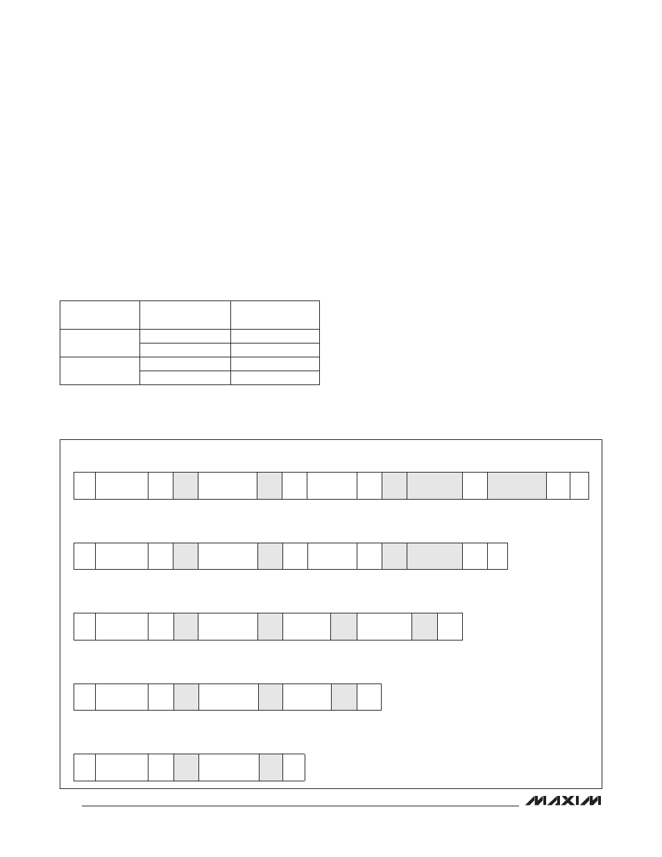
SMBus/PMBus Communication Examples
READ WORD FORMAT
1
7
1
1
8
1
1
7
1
1
8
1
8
1
1
S
SLAVE
ADDRESS
W
A
COMMAND
CODE
A
Sr
SLAVE
ADDRESS
R
A
DATA BYTE
LOW
A
DATA BYTE
HIGH
NA
P
READ BYTE FORMAT
1
7
1
1
8
1
1
7
1
1
8
1
1
S
SLAVE
ADDRESS
W
A
COMMAND
CODE
A
Sr
SLAVE
ADDRESS
R
A
DATA BYTE
NA
P
WRITE WORD FORMAT
1
7
1
1
8
1
8
1
8
1
1
S
SLAVE
ADDRESS
W
A
COMMAND
CODE
A
DATA BYTE
LOW
A
DATA BYTE
HIGH
A
P
WRITE BYTE FORMAT
1
7
1
1
8
1
8
1
1
S
SLAVE
ADDRESS
W
A
COMMAND
CODE
A DATA BYTE
A
P
SEND BYTE FORMAT
1
7
1
1
8
1
1
S
SLAVE
ADDRESS
W
A
COMMAND
CODE
A
P
A1
A0
7-BIT SLAVE
ADDRESS
100kI to V
SS
100kI to V
SS
1101 010 (D4h)
100kI to V
DD
1101 011 (D6h)
100kI to V
DD
100kI to V
SS
1101 100 (D8h)
100kI to V
DD
1101 101 (DAh)