Max9877, Applications information – Rainbow Electronics MAX9877 User Manual
Page 27
Applications Information
Filterless Class D Operation
Traditional Class D amplifiers require an output filter to
recover the audio signal from the amplifier’s output. The
filters add cost, increase the solution size of the amplifier,
and can decrease efficiency and THD+N performance.
The traditional PWM scheme uses large differential out-
put swings (2 x V
DD(P-P)
) and causes large ripple cur-
rents. Any parasitic resistance in the filter components
results in a loss of power, lowering the efficiency.
The MAX9877 does not require an output filter. The
device relies on the inherent inductance of the speaker
coil and the natural filtering of both the speaker and the
human ear to recover the audio component of the
square-wave output. Eliminating the output filter results
in a smaller, less costly, more efficient solution.
Because the frequency of the MAX9877 output is well
beyond the bandwidth of most speakers, voice coil
movement due to the square-wave frequency is very
small. Although this movement is small, a speaker not
designed to handle the additional power can be dam-
aged. For optimum results, use a speaker with a series
inductance > 10µH. Typical 8
Ω speakers exhibit series
inductances in the 20µH to 100µH range.
Component Selection
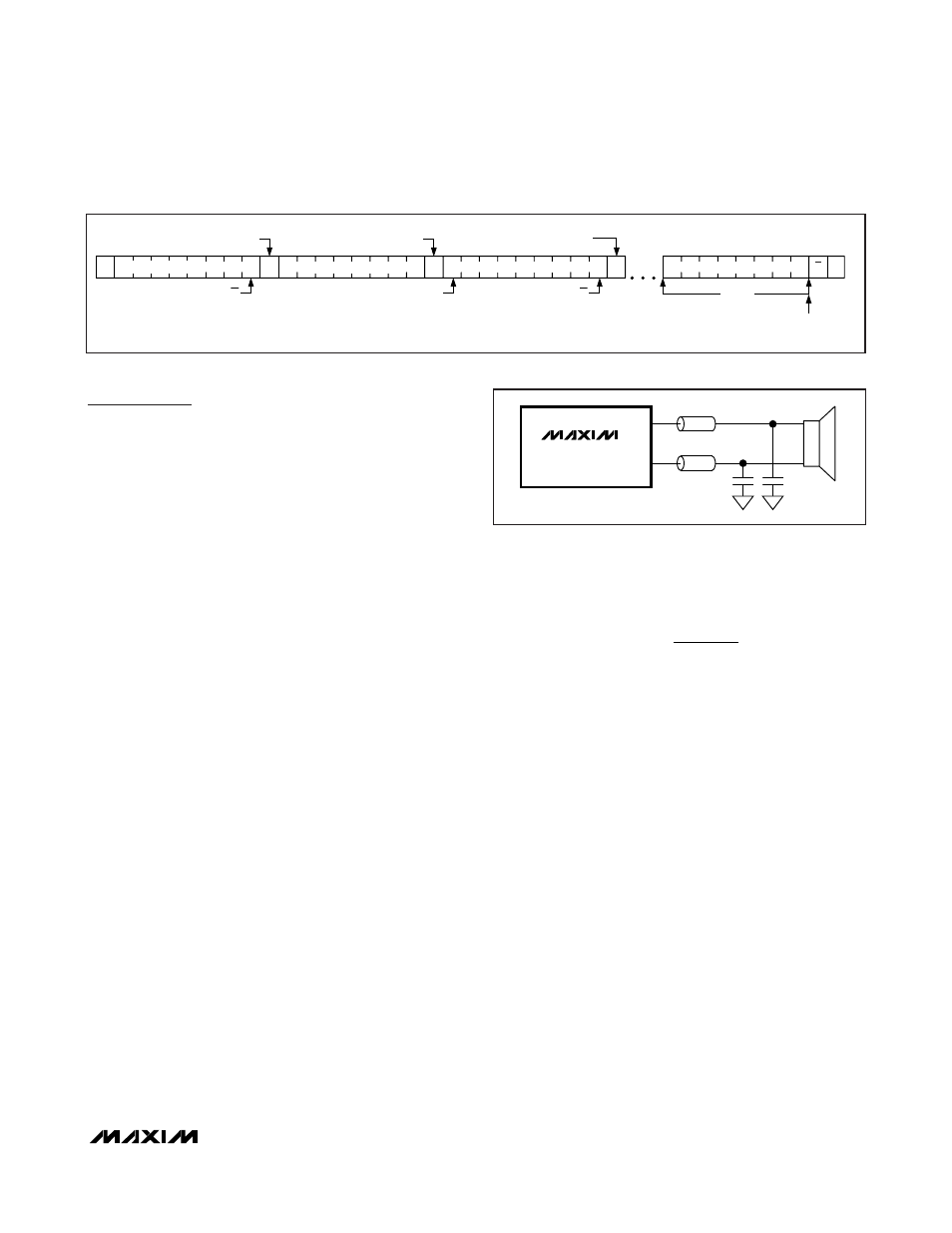
Optional Ferrite Bead Filter
In applications where speaker leads exceed 20mm,
additional EMI suppression can be achieved by using a
filter constructed from a ferrite bead and a capacitor to
ground. A ferrite bead with low DC resistance, high-
frequency (> 1.176MHz) impedance of 100
Ω to 600Ω,
and rated for at least 1A should be used. The capacitor
value varies based on the ferrite bead chosen and the
actual speaker lead length. Select a capacitor less than
1nF based on EMI performance.
Input Capacitor
An input capacitor, C
IN
, in conjunction with the input
impedance of the MAX9877 forms a highpass filter that
removes the DC bias from an incoming signal. The AC-
coupling capacitor allows the amplifier to automatically
bias the signal to an optimum DC level. Assuming zero
source impedance, the -3dB point of the highpass filter
is given by:
Choose C
IN
so that f
-3dB
is well below the lowest fre-
quency of interest. Use capacitors whose dielectrics
have low-voltage coefficients, such as tantalum or alu-
minum electrolytic. Capacitors with high-voltage coeffi-
cients, such as ceramics, may result in increased
distortion at low frequencies.
BIAS Capacitor
BIAS is the output of the internally generated DC bias volt-
age. The BIAS bypass capacitor, C
BIAS
, reduces power
supply and other noise sources at the common-mode
bias node. Bypass BIAS with a 1µF capacitor to GND.
Charge-Pump Capacitor Selection
Use capacitors with an ESR less than 100m
Ω for optimum
performance. Low-ESR ceramic capacitors minimize the
output resistance of the charge pump. Most surface-
mount ceramic capacitors satisfy the ESR requirement.
For best performance over the extended temperature
range, select capacitors with an X7R dielectric.
Flying Capacitor (C1)
The value of the flying capacitor (C1) affects the output
resistance of the charge pump. A C1 value that is too
small degrades the device’s ability to provide sufficient
current drive, which leads to a loss of output voltage.
f
R C
dB
IN IN
−
=
3
1
2
π
MAX9877
MAX9877
OUT+
OUT-
Figure 13. Optional Ferrite Bead Filter
ACKNOWLEDGE FROM MAX9877
1 BYTE
AUTOINCREMENT INTERNAL
REGISTER ADDRESS POINTER
ACKNOWLEDGE FROM MAX9877
A
A
A
P
0
ACKNOWLEDGE FROM MAX9877
R/W
S
A
R/W
REPEATED START
Sr
1
SLAVE ADDRESS
REGISTER ADDRESS
SLAVE ADDRESS
DATA BYTE
Figure 12. Reading n-Bytes of Indexed Data from the MAX9877
Low RF Susceptibility, Mono Audio
Subsystem with DirectDrive Headphone Amplifier
______________________________________________________________________________________
27