Directdrive headphone amplifier – Rainbow Electronics MAX9877 User Manual
Page 19
MAX9877
Low RF Susceptibility, Mono Audio
Subsystem with DirectDrive Headphone Amplifier
______________________________________________________________________________________
19
DirectDrive Headphone Amplifier
Traditional single-supply headphone amplifiers have
outputs biased at a nominal DC voltage (typically half
the supply). Large coupling capacitors are needed to
block this DC bias from the headphone. Without these
capacitors, a significant amount of DC current flows to
the headphone, resulting in unnecessary power dissi-
pation and possible damage to both the headphone
and headphone amplifier.
Maxim’s patented DirectDrive architecture uses a
charge pump to create an internal negative supply volt-
age. This allows the headphone outputs of the
MAX9877 to be biased at GND while operating from a
single supply (Figure 5). Without a DC component, there
is no need for the large DC-blocking capacitors. Instead
of two large (220µF, typ) capacitors, the MAX9877
charge pump requires two small ceramic capacitors,
conserving board space, reducing cost, and improving
the frequency response of the headphone amplifier. See
the Output Power vs. Load Resistance graph in the
Typical Operating Characteristics
for details of the pos-
sible capacitor sizes. There is a low DC voltage on the
amplifier outputs due to amplifier offset. However, the
offset of the MAX9877 is typically ±0.15mV, which, when
combined with a 32
Ω load, results in less than 10µA of
DC current flow to the headphones.
In addition to the cost and size disadvantages of the
DC-blocking capacitors required by conventional head-
phone amplifiers, these capacitors limit the amplifier’s
low-frequency response and can distort the audio sig-
nal. Previous attempts at eliminating the output-cou-
pling capacitors involved biasing the headphone return
(sleeve) to the DC bias voltage of the headphone
amplifiers. This method raises some issues:
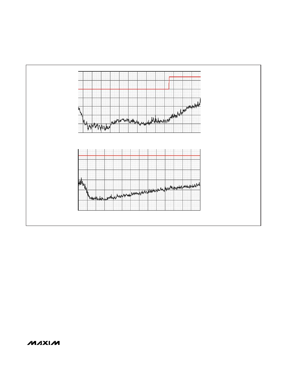
FREQUENCY (MHz)
AMPLITUDE (dB
μ
V/m)
160
140
120
100
80
60
10
15
20
25
30
35
40
TEST LIMIT
MAX9877 OUTPUT
MAX9877 OUTPUT
TEST LIMIT
5
30
180
200
240
260
280
300
220
FREQUENCY (MHz)
AMPLITUDE (dB
μ
V/m)
600
550
500
450
400
350
15
20
25
35
40
10
300
650
700
800
850
900
1000
950
750
Figure 4. EMI with 152mm of Speaker Cable