Rc2000 – Rainbow Electronics RC2000 User Manual
Page 2
RC2000
2005 Radiocrafts AS
RC2000 Shortform Datasheet (rev. 0.3)
Page 2 of 2
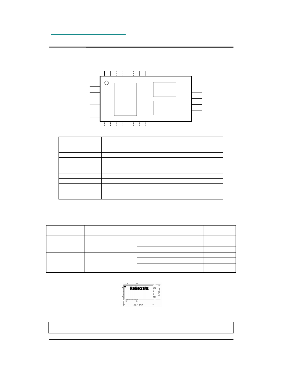
Block Diagram and Pinout
GND
CTS/RXEN/RXTX
RTS/TXEN
CONFIG
TXD
RXD
GND
GND
VCC
ON/OFF
VDD
GND
RF
GND
1
2
3
4
5
6
7
14
13
12
11
10
9
8
15 16 17 18 19 20 21 22
30 29 28 27 26 25 24 23
SD
A
SC
L
LN
A
_P
D
PA
_E
N
Communication
controller
RF Transceiver
Voltage
regulator
Pin Description
RXD
UART RX Data
TXD
UART TX Data
SDA
Transparent synchronous serial data I/O
SCL
Transparent synchronous serial data clock
CTS/RXEN/RXTX
UART Clear to Send, Receive Mode Enable, or UART RXTX
RTS/TXEN
UART Request to Send, or Transmit Mode Enable
CONFIG
Configuration Enable
RF
RF connection to antenna
VCC
Supply voltage input, unregulated
VDD
Supply voltage input, regulated
ON/OFF
Module on/off (shutdown)
GND
System ground
Note 1: In UART mode the TXD and RXD are used for serial data, and CTS and RTS for flow control (optional).
Note 2: In synchronous mode the SCL (data clock) and SDA (Data input and output) are used for serial data.
The RXEN and TXEN pins are then used to select the operation mode of the device. Signals are active low.
Note 3: The CONFIG pin is used to enter configuration mode (change of default settings).
Operating modes
Mode
Data interface
On air RF data
rate
FSK deviation
[kHz]
RX sensitivity
[dBm]
10 kbit/s
±
125
-101
250 kbit/s
±
250
-91
Buffered mode,
max 32 bytes
buffer
UART
0.6 – 19.2 kBd
RXD, TXD
1 Mbit/s
±
250
-87
10 kbit/s
±
125
-101
250 kbit/s
±
250
-91
Un-buffered
transparent mode
Synchronous
SDA, SCL
(UART used for
configuration mode only)
1 Mbit/s
±
250
-87
Mechanical Drawing
Mechanical Dimensions
The module size is 12.7 x 25.4 x 3.5 mm
Radiocrafts AS
, Gunnar Schjelderups vei 11, NO-0485 OSLO, NORWAY
E-mail:
Web site:
www.radiocrafts.com