The tc icon editor – TC Electronic P2 User Manual
Page 9
14
15
THE TC ICON EDITOR
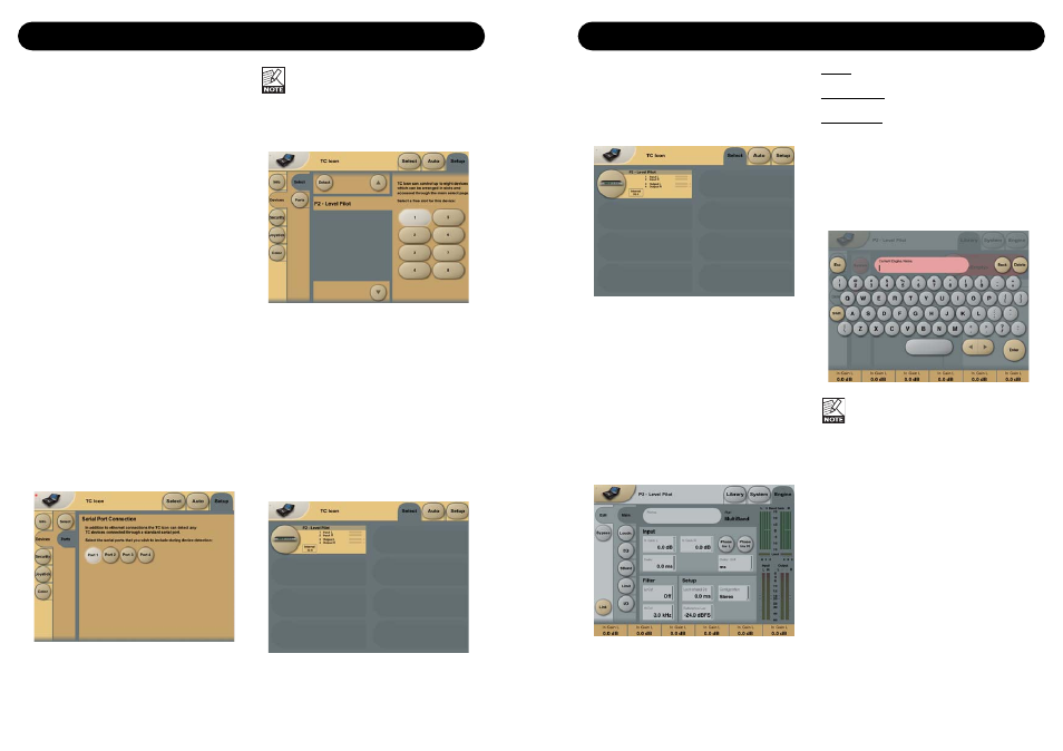
Basic Operation
The Icon Link key in the upper left corner
allows you to navigate between two main
pages/modes.
Fig 1 - Setup/Select page
Via the “overall” Select & Setup pages you
access overall settings and choices like:
• Selection of which connected unit to operate.
• Enable devices to network.
• TC Icon settings such as display and Fader-
appearance.
On the Select page illustrated above (Fig 1) all
connected units will appear. Press one of the
units indicated on that page.
Auto page
This page is redundant when operating a P2.
Fig 2 - Operating pages
Press the Icon Link key in the upper left corner
to select these pages.
These pages are relevant to one specific unit.
Library pages handle operations such as preset
Recall/Store and Delete.
System pages handle overall Clock Settings,
I/O settings and network settings.
Engine pages is where you control all algorithm
specific processing parameters.
Renaming presets
All user presets can easily be renamed.
Click on the CURRENT ENGINE NAME key on
the Store page and a keyboard display will
open.
The preset is not stored by entering the
name and pressing ENTER.
To actually store a preset the STORE key
must be pressed on the Store page.
Link
The LINK key allows you to assign any
algorithm parameter to any of the 6 Faders.
Thereby you are not limited to operate only the
parameters visible on the current page. You can
have e.g. In gain parameter from the Main page
on Fader 1 and the Loudness Level trim from
the Loudness page on Fader 2 etc.
To assign a parameter
• Press the LINK key.
• Select the Fader you wish to link a parameter
to, by pressing the field just above the fader.
• Press the parameter you wish to link to the
selected fader.
Introduction
The TC Icon Software Editor is a generic Editor
that currently controls the following products by
TC Electronic: System 6000, DB-8 and P2.
In this section only subjects relevant for usage
with the P2 will be discussed.
As described the P2 is connected via a serial
COM port. System 6000 and DB-8 are
connected via ethernet.
Navigating the Software Editor or TC Icon
display is easy as soon as a few basic
elements are explained.
Generally :
• Press the top-tabs to do primary selections.
• Press the side-tabs or elements to do
secondary selections.
• Press parameter value fields to instantly
assign parameters to Fader 6.
• Adjust values using Faders 1-6.
(also see LINK explanation on next page)
Unpacked and ready
• Connect according to illustrations on page 10.
Note to which COM port you connect the P2.
• Install software according to explanation on
the previous page of this manual.
• Power up the P2 and start the TC Icon
software on your computer.
• Go to the Select/Port page to select which
COM(1-4) port you you have connected to.
• Select Port.
(Note that the first time you open the Setup
Port page all COM-ports 1-4 are selected).
Another active application may conflict
with the selected COM Port. If this is the
case you should close that application or
connect the P2 to another COM port.
Also see Trouble-shoot section in this manual
• Then go to the TC Icon Setup/Devices page.
• Press the DETECT key. The TC Icon Editor
will scan the System and find the connected
P2’s.
• When the connected P2 is detected, assign
the unit to one of the eight shortcut keys in
the right side of the display, by pressing one
of the eight keys (see above). Any key will
do. When several units are connected this
page serves as a convenient organizer for
the entire system.
• Go to the Select page (top-tab), and you will
see a screen similar to the one below
depending on number of connected units and
in which locations you have assigned them.
• Press the large P2 key.
• TC Icon now retrieves data from the P2.
• When ready you will see the Main operating
display.
THE TC ICON EDITOR