System - net page & icon views, I/o page – TC Electronic P2 User Manual
Page 13
22
23
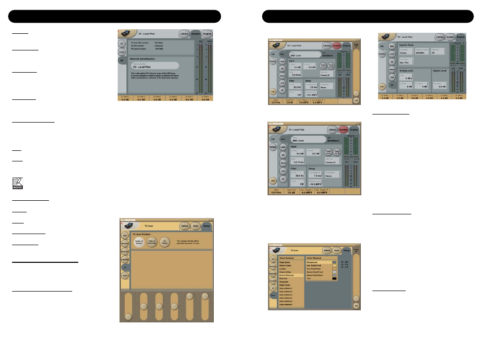
SYSTEM - NET PAGE & ICON VIEWS
The upper part of this page holds information
on the current software versions and the serial
number of the accessed unit.
Network identification
A simple naming function that enables you to
name each connected unit.
UI - Icon Views
On the Icon Setup page two sub-pages are
available for controlling the TC Icon
appearance.
Fader appearance
Three options are available. Changes will take
place next time you open the TC Icon.
Faders at bottom
Fader at right side
No faders
Color Page
Select a color scheme to your liking or make
your own.
I/O PAGE
Input & Clock
Input Select
Range: Analog, Digital
Select appropriate Input type.
Digital Input Select
Range: AES/EBU, S/PDIF
Select type of digital Input format.
Clock Select
Range: Internal 44.1, Internal 48k,
Word Clock, Ext DI
Select to which clock the P2 should sync.
Digital SRC
Range: On/Off
Sets whether the P2 should perform Sample
Rate conversion on the incoming clock or not.
Analog Levels
Analog Scale
Range: -3 to +27dBu @ Full scale
Sets Analog Input sensitivity.
Analog In Offset
Range: -3 to +25dBu @ Full scale
Sets Analog Input level.
Analog Out Offset
Range: -3 to +24 dbu @ Full scale
Adjusts Analog Output gain to match
downstream device.
Digital Level
Digital Out Offset
Range: -12dB to 0dB
The Digital Out Offset parameter controls the
Digital Output level in accordance to the set
Analog Scale Output level.
Disable:
No lock function is active.
Lock Wizard:
Wizard function is disabled and cannot be
activated via the front panel WIZARD key.
Lock Recall:
No presets can be recalled via the eight front
panels preset keys but the Wizard function is
enabled.
Lock Panel:
The entire front panel, recall functions, Bypass
and Card dump functionality is disabled.
Lock Activation
The two Lock activation modes defines how the
Lock function can be activated/deactivated from
the front panel.
Hold
: Lock/unlock can be done by holding
Lock key for 2 seconds
Code
: Four digit code entered via the
eight front panel controls is needed
to unlock front panel controls.
The unlock code must be entered within
5 seconds.
Bypass Mode
Press the round BYPASS key to activate.
Normal
: No Delay in bypass and
Dither is active
Relay
: Bit transparent digital and
analog Bypass Relay
No Codec Delay : No delay in bypass.
Bypass bit transparency.
Codec Delay
: Delay active in Bypass.
Bypass bit transparency.
Lock Code/Unlock Code
Enter the lock/unlock codes that needs to be
entered to lock/unlock front panel controls when
in Lock mode (see above).
Yellow LED Threshold
Analog In, Analog Out & Out Threshold
Range: 0 to - 20dB
Sets the response Threshold for the two yellow
digits in the In/Out meters.