Cloning p2’s, System - i/o page – TC Electronic P2 User Manual
Page 11
18
19
CLONING P2’S
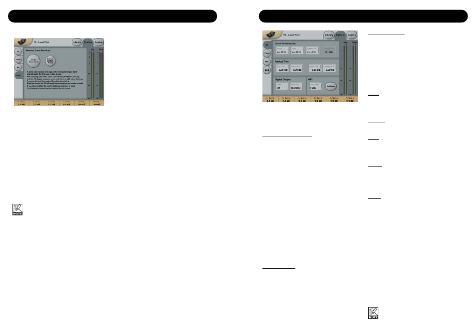
Cloning P2’s
Creating the Clone Card
To easily clone multiple P2’s a PCMCIA card is
used.
• Load appropriate presets into Front Panel
Bank of the P2 you wish to clone.
• Insert a 512kb or 1Mb PCMCIA card in the
Card slot on the P2 front panel.
• Go to the System Card page.
• Decide whether you wish to exclude System
Preset 1 that holds overall Clock settings,
Analog Trim levels, Dither, Status Bit settings
and settings for GPI.
To exclude System Preset activate the
“Exclude System Preset” key.
• Press the CREATE CLONE CARD key on
the System/Card page.
•
Please note following: ALL DATA
previously stored on the card will be
destroyed when formatting the card.
•
If the card is write-protected no data
can be written on the card. The
protect/un-protect- switch is located
at the edge of the card.
Loading/Cloning P2 using the Clone Card.
Once the clone card has been created on the
P2 hooked up via the TC Icon PC Editor it is
time to transfer the card data to other P2’s in
your facility.
• Insert the PCMCIA card in the “target” P2.
• Press and hold the LOCK key while powering
up the P2.
• Press the LOCK key again. In this mode the
LOCK key operates as “CONFIRM”.
BYPASS can be used to abort operation.
• The target P2 is now loaded with the
information present on the card.
SYSTEM - I/O PAGE
Parameters on the System page can be
stored and recalled via System presets and
are unaffected by normal Recall operations.
Clock Preferences
Analog
Range:
Internal 44.1kHz
Internal 48kHz
Ext. W. Clk. (External Word Clock)
Ext. DI
Sets the processing clock frequency when
analog Inputs are used.
Digital
Range:
Internal 44.1kHz
Internal 48kHz
Ext W Clk (External Word Clock)
Ext. DI
Sets processing clock frequency when
processing signal on the AES or S/PDIF Inputs.
Digital w. SRC
Range: Internal
44.1kHz
Internal 48kHz
Ext Word Clock
Sets the processing clock frequency when
Digital SRC is selected on the Engine I/O page.
Analog Trim
Input Trim L & Input Trim R
Range: 0.05 to 41dB
Level trim for Analog Inputs
Output Trim L & Output Trim R
Range: 0.05 to 41dB
Level trims for Analog Outputs.
Digital Output
Dither
Range: 8, 12, 14, 16, 18, 20, 22, 24, off
P2 processes internally at 48 bit resolution.
Dither must be set to match downstream
devices.
Status Bits
Select whether the P2 should send out
AES/EBU or S/PDIF status bit information.
GPI
Via an external Fader or alternating (latching)
switch various functions can be controlled.
GPI Assign
Disabled
Connected device to GPI is disregarded.
Fader
Connect e.g. a TC Master Fader (not included)
to control the Master Out level parameter.
(see calibrate section next page).
Bypass
Connect an alternating (latching) switch to
remote control Bypass function. Note that the
Bypass function is defined on the System Front
page. (see calibrate section next page).
Preset
Range: 2 presets, 4 presets or 8 presets
Selection between up to 8 presets (equivalent
to the Front Panel recall keys) is achieved by
feeding the processor a DC voltage to its 1/4"
jack input. The Input voltage is compared
against voltage windows that correspond to
certain presets.
Between the valid voltage windows, invalid
windows have been inserted to protect against
erratic operation. The processor constantly
monitors the GPI Input, and only if several
consecutive measurements point to the same,
valid voltage window, a recall is performed.
The voltage windows chosen enable easy
"binary relay encoding" as shown on the next
page in fig. 1. If long cable runs are required,
HF decoupling using a ceramic capacitor
across the Tip and Sleeve terminals inside the
jack plug may be indicated.
The ring terminal of the 1/4" jack is not
used.