Card overview – Cobalt Digital COMPASS 9212-EO 3G_HD_SD-SDI Fiber Transmitter User Manual
Page 24
3-2
••••
User Controls
9211-OE, 9212-EO User Manual
Card Overview
This section provides a general overview of the 9211-OE and 9212-EO components. For
information on the LEDs available on the card-edge, refer to the section “Control and
Monitoring Features”.
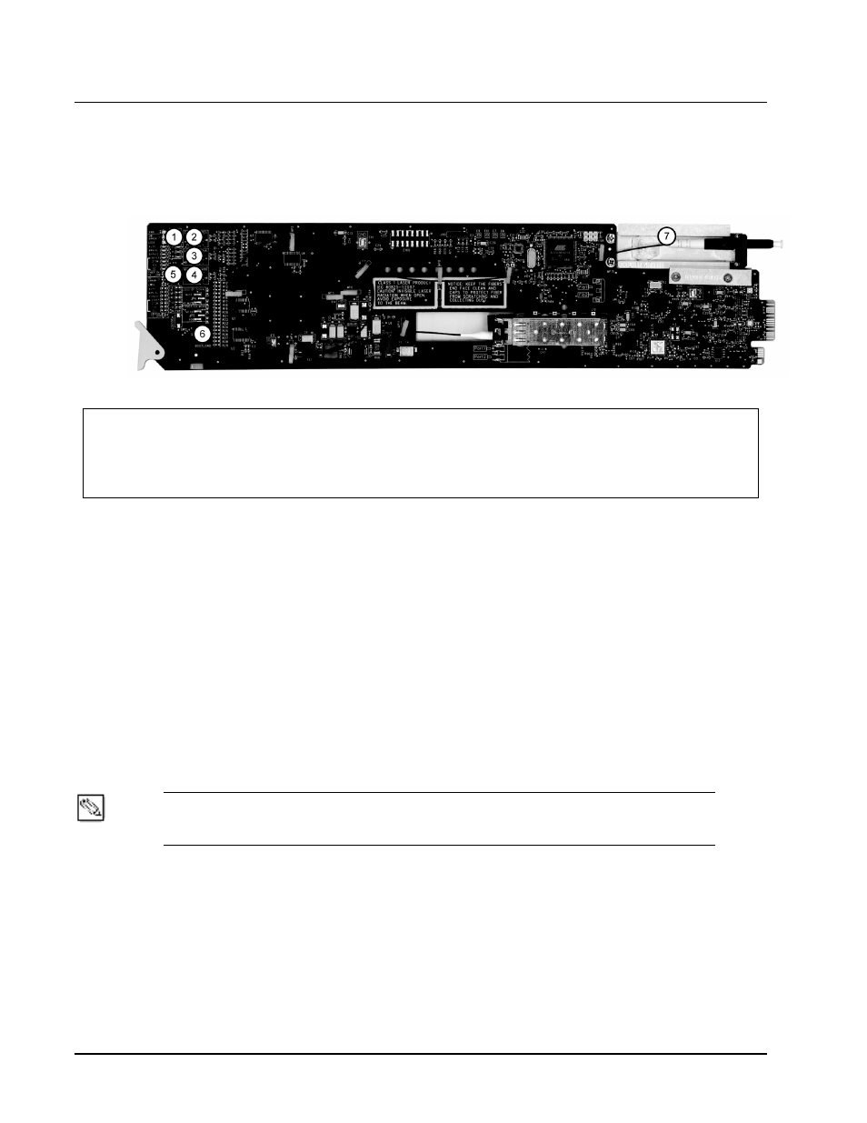
Figure 3.1
9211-OE and 9212-EO — Components
1) Rx Power LEDs - Channel A
5) Select Switch - Channel A (SW1)
9) Select Switch - Channel B (SW2)
2) Card Control (JP1)
6) Rx Power LEDs - Channel B
10) Bootload Button (SW3 )
3) Loss of Signal - Channel A (JP2)
7) Loss of Signal - Channel B (JP4)
11) Fiber Optic Connector
4) Bypass EQ Mode - Channel A (JP3)
8) Bypass EQ Mode - Channel B (JP5)
1. Rx Power LEDs
In this area of the 9211-OE, five LEDs are available to indicate the input optical power as detected
by the optical module. Refer to the section “Rx Power LEDs on the 9211-OE” for details.
2. Error! Reference source not found.
Use
JP1
to select whether the card is remotely configured (for example, via DashBoard or
SNMP). You can select one of the following options:
•
REMOTE — This option enables the remote configuration. All parameters may be
configured remotely. Data rate selection can also be configured locally using
SW1
,
however, the jumper settings (
JP2
and
JP3
) are ignored.
•
LOCAL — This option disables the remote configuration. The card can only be
configured using the card-edge controls (
SW1
,
JP2
, and
JP3
). This option is useful to
lock out remote configuration changes. This is the default setting.
Note
— The card status and configuration can still be monitored remotely when JP1 is
set to LOCAL.
3. Error! Reference source not found.
Use
JP2
to determine the card behavior on a loss of input. Note that the
JP2
setting is only used
when
JP1
is set to LOCAL. You can select one of the following options: