9211-oe cabling overview – Cobalt Digital COMPASS 9212-EO 3G_HD_SD-SDI Fiber Transmitter User Manual
Page 20
2-6
••••
Installation and Setup
9211-OE, 9212-EO User Manual
Cabling for the 9211-OE and 9212-EO
This section provides information for connecting cables to the installed Rear Modules on a 20-slot
frame. Connect the input and output cables according to the following sections.
The optical connector used to mate the card to the rear module is designed for blind mate optical
connections. All fiber interfaces are single mode fibers.
Notice
— Every time you are required to insert a connector into a device, or mating
sleeve, you must clean the connector. All exposed surfaces of the ceramic ferrule must
be clean. Follow your facility practices of cleaning fiber optic connectors.
Connectors must always be inserted into a device or have a dust cap on.
9211-OE Cabling Overview
In a 20-slot frame, the 9211-OE is used with the following Rear Modules:
•
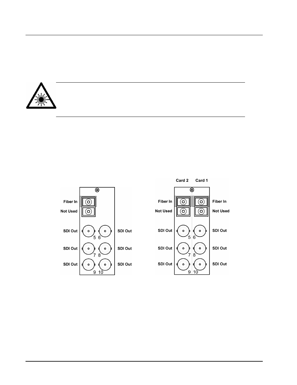
RM20-9211-B Full Rear Module — Each 9211-OE occupies two slots and provides an
optical input, and six SDI outputs. Refer to Figure 2.5.
•
RM20-9211-B/S Split Rear Module — Each 9211-OE occupies one slot and provides one
optical input, and three SDI outputs. Refer to Figure 2.6.
Figure 2.5
Cable Connections for the RM20-
9211-B Rear Module
Figure 2.6
Cable Connections for the RM20-
9211-B/S Rear Module