Cobalt Digital COMPASS 9212-EO 3G_HD_SD-SDI Fiber Transmitter User Manual
Page 18
2-4
••••
Installation and Setup
9211-OE, 9212-EO User Manual
5.
Align the top hole of the Rear Module with the screw on the top-edge of the frame back plane.
6.
Using a Phillips screwdriver and the supplied screw, fasten the Rear Module to the back
plane of the frame. Do not over tighten.
7.
Ensure proper frame cooling and ventilation by having all rear frame slots covered with
Rear Modules or Blank Plates.
This completes the procedure for installing a Rear Module in your 8321 series frame.
Installing the 9211-OE and 9212-EO
Use the following procedure to install the 9211-OE or 9212-EO in a 20-slot frame:
1.
Locate the Rear Module you installed in the procedure “Installing a Rear Module”.
2.
Ensure that the Rear Module is one of the required rear modules for the 9211-OE or
9212-EO. You must use either a Full Rear Module or a Split Rear Module.
3.
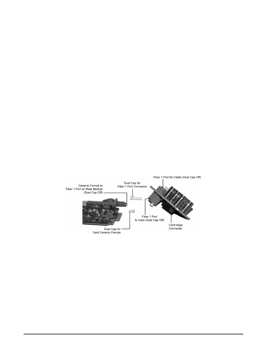
Remove the dust caps from the Fiber 1 oort connector on the card end.
•
Refer to Figure 2.1 and Figure 2.3 for connector location.
•
Refer to the section “Important Laser Safety Measures and Notices”at the
beginning of this manual for safety information when handling fiber optic
components.
Figure 2.3 Card Connectors with Dust Caps Removed
4.
Ensure that the exposed surface of the ceramic ferrule of the connectors is clean. Refer to
the section “Working with Fiber Optic Connectors” for cleaning tips.
5.
Hold the card by the edges and carefully align the card-edges with the slots in the frame.
6.
Fully insert the card into the frame until the rear connection plus is properly seated in the
Rear Module. You will feel a click when the card mates onto the rear module.
7.
Affix the supplied Rear Module Label, as per the included instructions, to the BNC area
of the Rear Module.