Installing a rear i/o module, Installation and setup – Cobalt Digital COMPASS 9362 HD_SD-SDI Test Signal Generator User Manual
Page 23
9362-OM (V4.1)
9362 PRODUCT MANUAL
2-3
Installation and Setup
Installing a Rear I/O Module
Note:
If installing a card in a frame already equipped for, and connected to
DashBoard™, no network setup is required for the card. The card will be dis-
covered by DashBoard™ and be ready for use.
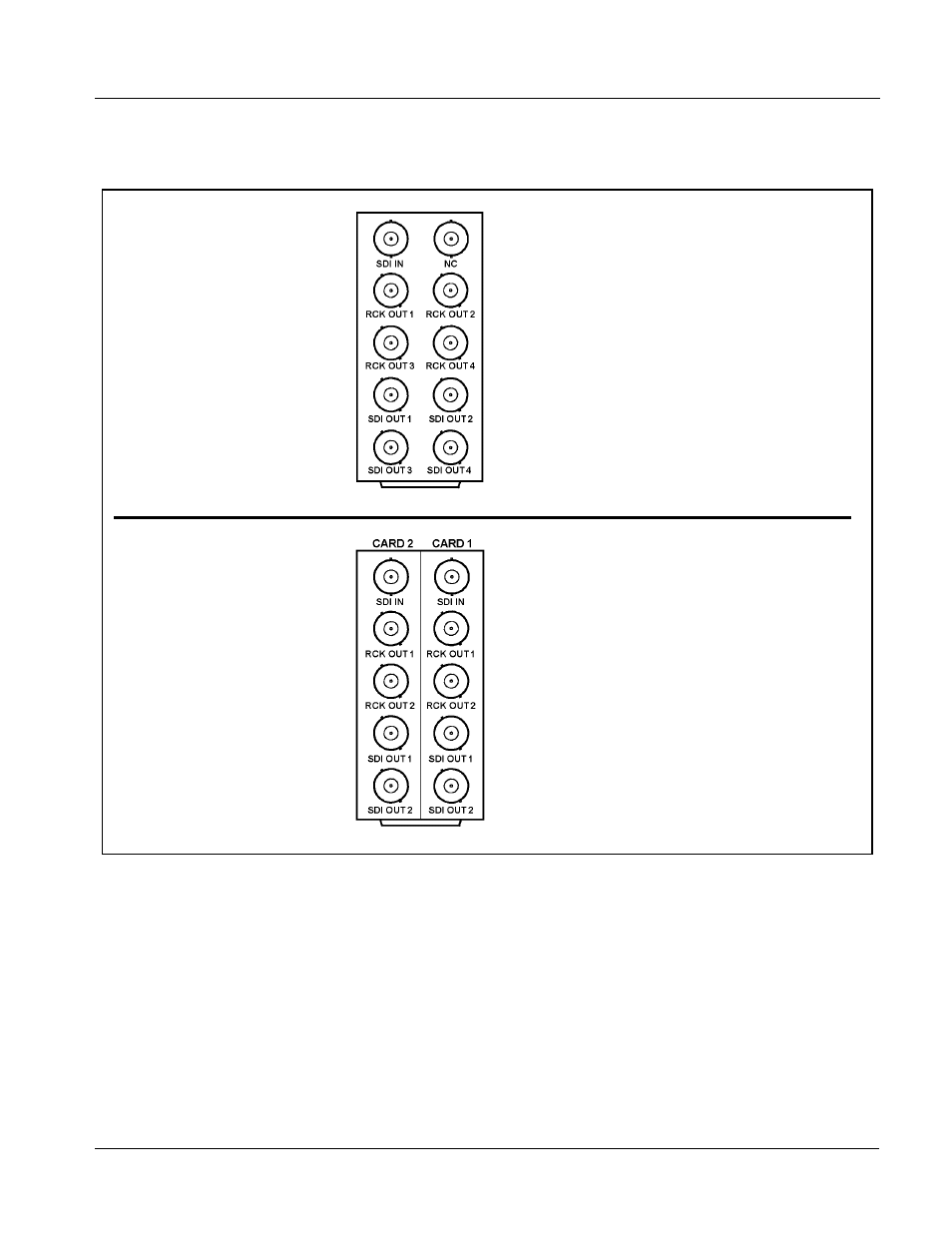
Figure 2-1 9362 Rear I/O Module Connections
Installing a Rear I/O Module
Note:
This procedure is applicable only if a Rear I/O Module is not currently
installed in the slot where the 9362 is to be installed.
If installing the 9362 in a slot already equipped with a suitable I/O module,
omit this procedure.
Rear module RM20-9362-A Rear I/O Module use the
connector arrangements shown to the left and described
below.
• HD/SD-SDI coaxial input (SDI IN)
• Four HD/SD-SDI reclocked input copies (RCK OUT 1 thru
RCK OUT 4)
• Four buffered SDI coaxial outputs (SDI OUT 1 thru
SDI OUT 4)
Connect cabling as shown. Unused connectors do not
require external termination.
RM-9362-A.PNG
Where a maximum of five BNC connections can suit
particular I/O requirements, a “split” Rear I/O Module offers
maximum card density within the frame by accommodating
two cards using a module occupying no more area than a
standard module. The RM20-9362-A/S shown here provides
each of the following connections for two 9263 cards as
described below.
• HD/SD-SDI coaxial input (SDI IN)
• Two HD/SD-SDI reclocked input copy (RCK OUT 1) and
RCK OUT 2)
• Two buffered SDI coaxial outputs (SDI OUT 1 and
SDI OUT 2)
Viewed from the rear, the right
column of BNC connectors
accommodates the right-most card,
with the left column accommodating
the adjacent card to the left.
In this example with two 9362 cards in
slots 1 and 2, the right column serves
9362, slot 1 and the left column
serves 9362, slot 2.
RM-9362-AS.PNG