Vellum, F1 f2, I/d or direct – Peerless Lighting VMM9 - LED User Manual
Page 2: Suspended, Vmm9
2246 5th Street, Berkeley, CA 94710
•
Tel: 510.845.2760
•
Fax: 510.845.2776
•
P
INTEGRATED NLIGHT MICRO SENSOR
47”
95”
97
3
/
16
”
49
1
/
8
”
4
1
/
2
”
2
7
/
8
”
VIEW FROM TOP
VIEW FROM TOP
VIEW FROM BOT TOM
9 ”
9 ”
Determine the appropriate sensor type, network type and sensor power source for your application. Enter the code in the Options section of the Catalog Number.
EXAMPLE:
PDT1
Sensor Type (choose one)
ADC
nLight model
nES ADCX
Daylight Dimming
No occupancy sensing
PDT
nLight model
nES PDT7 ADCX
Daylight Dimming and Occupancy Detection
For more information about the Integrated nLight Micro Sensor, its capabilities and options, do
*nLight-Enabled (network-ready) options include one RJ-45 connector on the luminaire, 10 feet of Cat-5e cable to control the entire luminaire row (depending on
wattage/voltage limitations), and splitter. The Cat-5e cable drop is located in the same section as the sensor. For multiple zones, please contact [email protected].
Type:
________________________
Project:
______________________
Suspended
VMM9
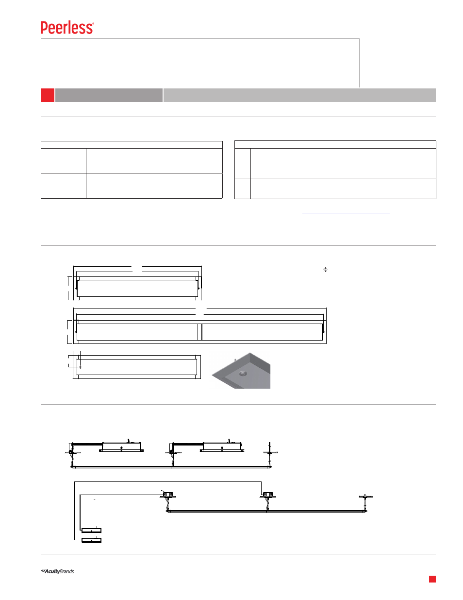
REMOTE DRIVER MOUNTING
WEIGHTS, SUPPORT SPACING & SENSOR LOCATION
Vellum
LED
I/D or Direct
Suspension spacing equals section length.
2
© 2014 Acuity Brands Lighting, Inc. All Rights Reserved. “Peerless” is a registered trademark of Acuity Brands Lighting.
Products in this document may be covered by one or more U.S. Patents and Patents Pending. Specifications subject to change without notice.
5-year limited warranty. Complete warranty terms locatx
I/D or Direct
VMM9 Vellum LED
Network Type & Sensor Power Source (choose one)
1*
nLight-Enabled (Network-Ready) with Power Pack in remote driver box
10’ Cat-5e cable and splitter provided
STANDARD SECTIONS
4’-
1
⁄
4
”
4’-6
1
⁄
4
” O.A.
3” for end cap
2”
8’-6” O.A.
8’-0”
PLAN VIEW
Key:
•
Support or feed location
Sensor
10 LBS
20 LBS
The driver is housed in a remote-mounted, aluminum enclosure. In T-bar ceiling installations, the driver enclosure attaches to the grid bars with provided hanging brackets and clips.
For hard ceiling installations, the driver enclosure resides inside an electrical room and can be mounted to a rack or wall with screws (by others), if necessary. NOTE: Every 4’ and 8’
luminaire section comes with (1) driver enclosure and each section has (1) driver feed leading out of the luminaire. See installation instructions for further details.
F1
F2
LUMINAIRE
DRIVER ENCLOSURE
BUILDING WIRE
DRIVER ENCLOSURE
BUILDING WIRE
D.C. CONNECTION
WIRES
(BY OTHERS)
OCTOGONAL JUNCTION BOX
BUILDING WIRES
DRIVER ENCLOSURES IN ELECTRICAL ROOM
LUMINAIRE
F1
F2
LUMINAIRE
DRIVER ENCLOSURE
BUILDING WIRE
DRIVER ENCLOSURE
BUILDING WIRE
D.C. CONNECTION
WIRES
(BY OTHERS)
OCTOGONAL JUNCTION BOX
BUILDING WIRES
DRIVER ENCLOSURES IN ELECTRICAL ROOM
LUMINAIRE
F1
T-Bar
Ceiling
F2
Hard
Surface
Ceiling