Electronics AC User Manual
Page 12
12
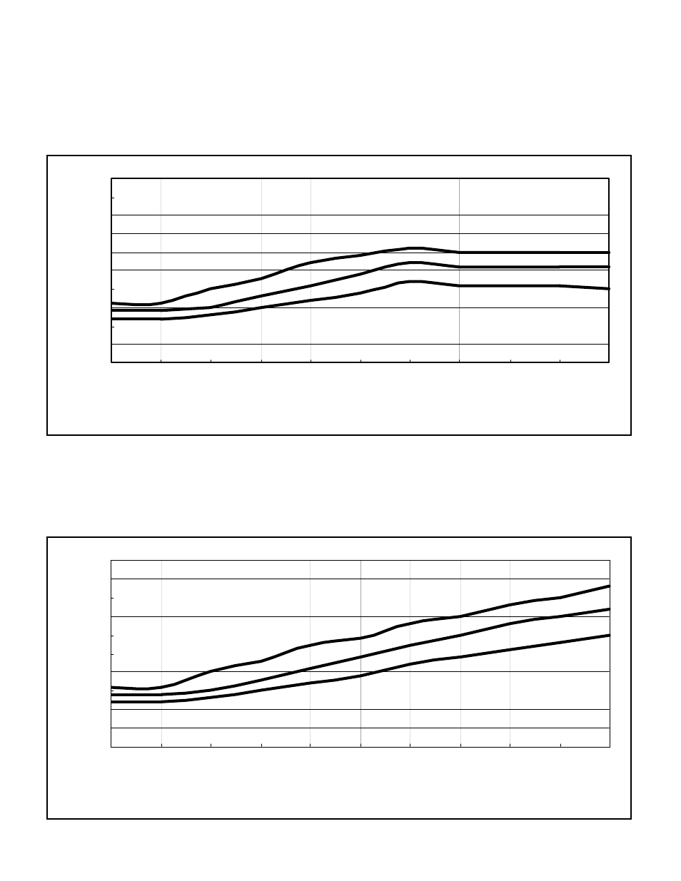
The following graphs show the results from two types of shot flow rate conditions. The first shows a
condition where the maximum amperage is too low due to restricted maximum shot flow rate. This
can be caused by inadequate sizing of the openings in the shot hopper or contamination (blockage)
either above or below the MagnaValve. This could also be caused by restrictions at the wheel inlet
due to pipe size or the wheel not being sized properly to discharge enough media at a given motor
RMP.
0
5
10
15
20
25
30
35
40
45
50
0
10
20
30
40
50
60
70
80
90
100
% Setpoint
Mo
to
r A
m
p
s
0
5
10
15
20
25
30
35
40
45
50
0
10
20
30
40
50
60
70
80
90
100
% Setpoint
Mo
to
r A
m
p
s
The second example shows a typical installation where the full load (FL) motor current of 35 A is
achieved at approximately 70% of MagnaValve capacity with the wheel running at 3000 RPM. This in-
dicates that the valve is able to supply all the shot needed and has a reserve capacity of 30%.
Caution
: Do not allow operation above the full load rating of the motor.