Electronics AC-24 User Manual
Page 9
9
E. Motor amps are erratic or unstable.
1. New installations - refer to servo adjustments.
2. Old installations - machine worked fine until recently.
3. Check shot for cleanliness (dust, oil, water).
4. Check shot for obstructions.
5. Check shot hopper, are you low or out of shot?
6. Do not adjust servo adjustments.
7. Check for worn wheel blades or worn control cage.
8. Call the factory for advice.
F. Amperage calibration not accurate at low or high amps
1. If the amperage on the digital display matches the actual motor current at a low setting
but not at a higher setting you should compare the motor amps with a clamp-on type
ammeter to the current transformer output. If it is not proportional then the wire size for
the current loop is too small and must be increased. Up to 5 foot long wire loops can
use 16 AWG wire. Longer runs should use 14 AWG or 12 AWG wire.
G. System Profile
1. If you cannot achieve expected high motor amperage or the system “just isn’t right”,
you should perform the following profile before calling for help. This procedure will pro-
vide the information needed for corrective action.
2. Put the Servo “Off” (2-20).
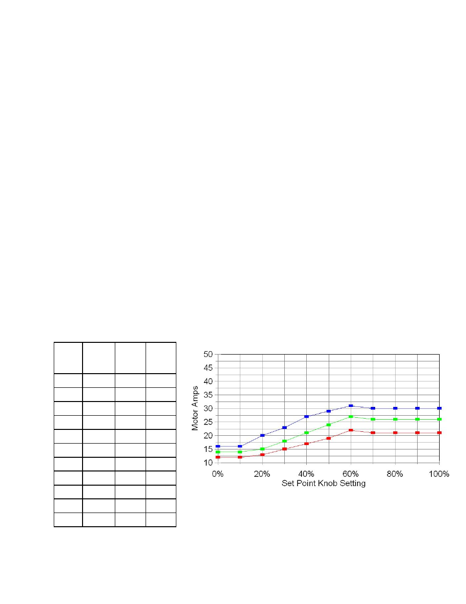
3. Use the setpoints in the following table.
4. Read and record the amperage reading for each of these setpoints in the forms avail-
able at the end of the manual. FAX this information back to Electronics Incorporated for
assistance. (1-574-256-5222)
12.
EXAMPLES
A. The following graphs show the results from two types of shot flow rate conditions. The first
shows a condition where the maximum amperage is too low due to restricted maximum
Set
Point
Knob
Wheel
RPM
1750
Wheel
RPM
2400
0% 12 14 16
10% 12 14 16
20% 13 15 20
30% 15 18 23
40% 17 21 27
50% 19 24 29
60% 22 27 31
70% 21 26 30
80% 21 26 30
90% 21 26 30
100% 21 26 30
Wheel
RPM
3000