Rough Country 683X User Manual
Page 7
28. Tighten all 3/8” hardware using a 9/16” wrench.
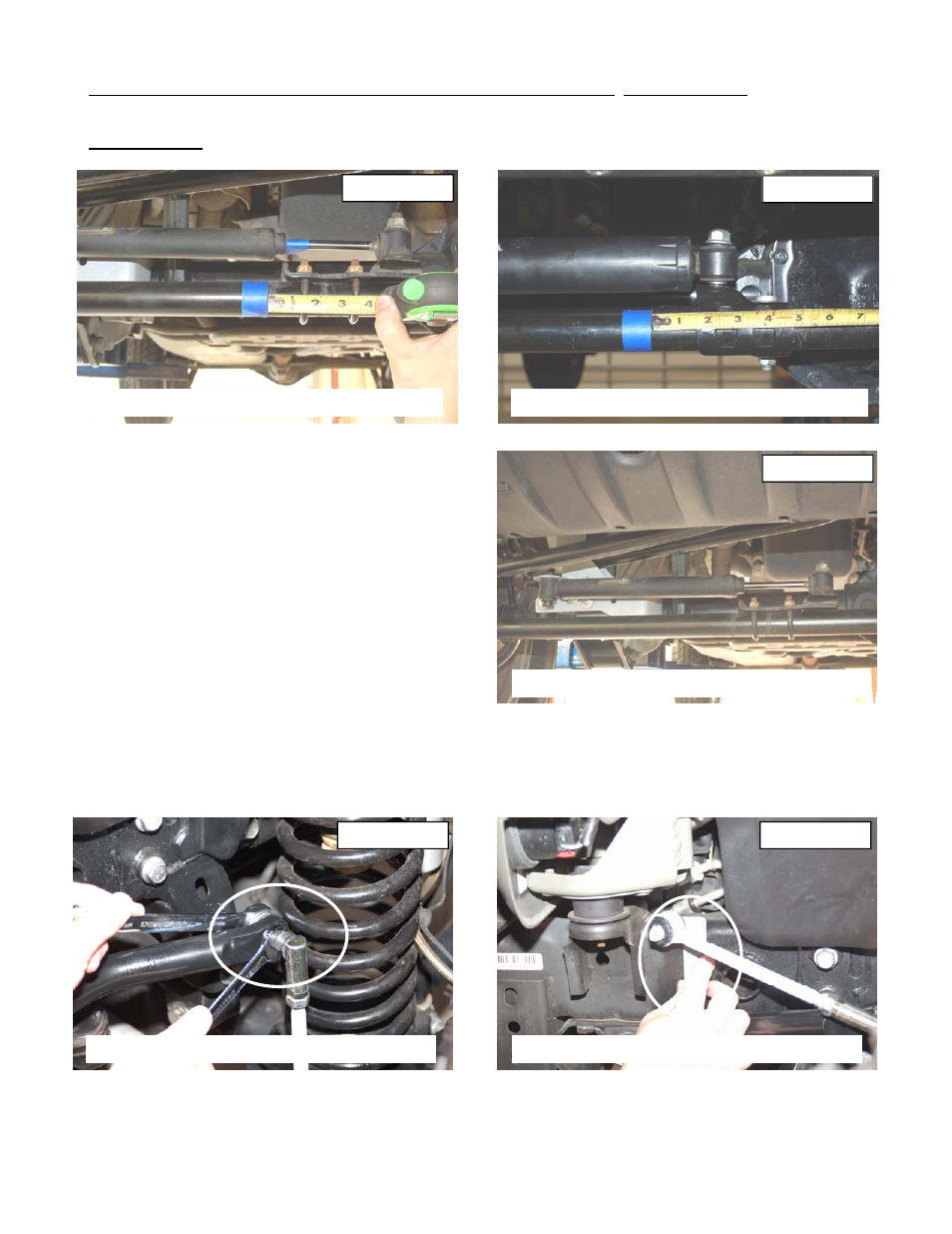
29. This next two steps will be performed if the stock stabilizer is retained. On 07-10 Models mark the location on
the factory tie rod bracket on the tie rod and loosen the u-bolt nuts using a 13mm wrench. Slide the bracket down 1
1/4” rotate to position the stud up as shown and retighten tie rod end bracket. See Photo 18.
30. On 2011 models loosen the tie rod bracket using a 15mm wrench. Mark original location and move the bracket 1
1/2” and rotate the tie rod bracket as shown to allow full stroke of the stabilizer cylinder. See Photo 19.
31. Install the factory stabilizer in the new track rod / stabilizer
mount with the body of the stabilizer on the axle mount
with stock hardware and tighten using a 18mm socket /
wrench. See Photo 20
32. Assemble the bushings/sleeves in the track rod and adjust
to a length of 32 7/8” center of hole to center of hole. In-
stall the new track bar into stock frame bracket using the
stock hardware.
33. Check to make sure the body is centered over the axle
and install the stock track bar into the new track rod
bracket using the supplied 14mm x 80mm bolt, washers
and lock nut. Tighten using a 21mm & 22 mm socket /
wrench. Torque all fasteners to specifications. It may be
necessary to turn the steering wheel to align the
track rod end with the axle.
34. On the front sway disconnects, assemble the supplied jam nut and end link on the sway bar link body. Adjust the
sway bar to approx 11” for a 4” & 6” kit measuring end to end. Tighten the end and jam nut using a 18mm wrench.
35. Install the new sway bar link on the factory sway bar as shown in Photo 21 with the supplied 12mm Flange lock nut
using a 16mm & 18mm wrench.
36. Install the new sway bar link on the sway bar bracket and swing up the assembly to the frame rail. See Photo 22.
Remove the sway bar link from the bracket while holding the bracket in place.
Photo 21
Install upper end on sway bar
Photo 22
Position bracket to be drilled
PHOTO 18
MOVE STABILIZER BRACKET
PHOTO 19
PHOTO 20
INSTALL STOCK STABILIZER IN MOUNT
2011 STAB BRACKET SHOWN