Rough Country 481.20 User Manual
Page 4
20. Using a 18mm socket and wrench, install the shock absorbers in the factory location, part # 650328 hydraulic/
650380 gas charged shock using hardware included in kit. Tighten the upper shock nut and lower bolt to 75 ft/lbs.
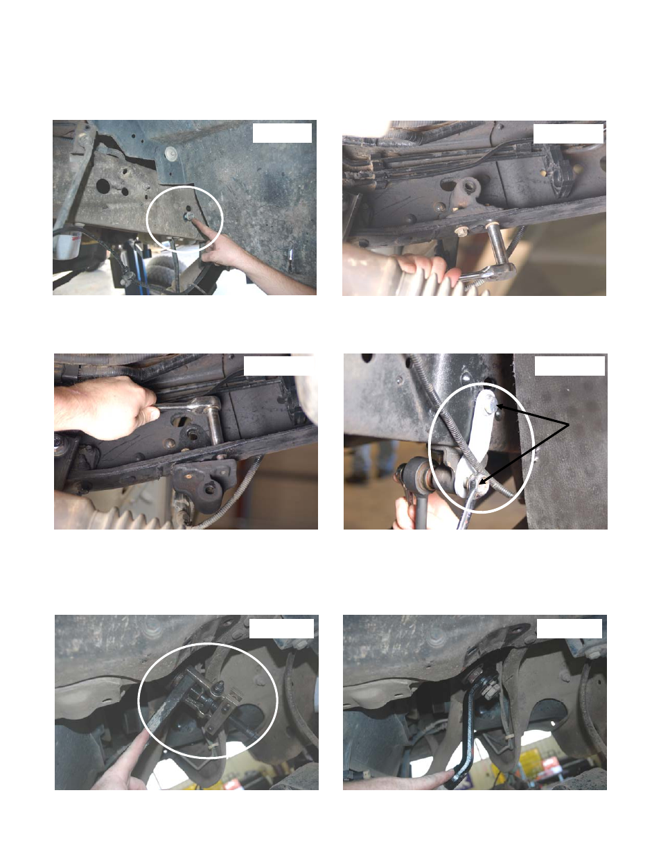
21. Remove the factory anti-sway bar frame brackets (where the upper end of the sway bar link attaches to the frame).
Save all the hardware for reuse. See PHOTO 10.
24. Using a 13mm wrench, remove the factory anti-sway bar frame brackets (where the upper end of the sway bar link
attaches to the frame). Save all the hardware for reuse. See PHOTO 11.
25. Attach the new anti-sway bar drop brackets to the frame in the same location as the original brackets using the sup-
plied 1/2” x 1 1/2” bolts, washers / nuts and tighten using a 18mm socket / wrench. See Photo 12.
26. Using a 18mm socket, and 15mm wrench, attach the upper ends of the factory anti sway bar links to the new brack-
ets using the supplied 12mm x70mm bolt and 12 mm stover nut. Tighten to 37 ft/lbs. See PHOTO 13.
27. Remove the cotter pin and nut using a 21mm wrench, from the drag link end where it attaches to the pitman arm.
Dislodge link with a tie rod end puller, or a pickle fork. See PHOTO 14. Note: replace the link if any stud looseness is
detected, or if you can twist the studs in its socket with your fingers. Using a 34mm socket, remove the nut from the
steering sector and remove the pitman arm with a puller tool. Inspect the splines on the shaft for excessive wear,
repair if needed.
28. Install new arm, lock washer, and nut. Using a 34mm socket, torque to 200 ft/lbs. See PHOTO 15.
Photo 10
Photo 14
Photo 15
Photo 13
Photo 11
Photo 12