Powerboard, Installation instructions, Troubleshooting – Rough Country 75105-15 User Manual
Page 8: Service tips linkage component identifi cation
PowerBoard
®
– Installation Instructions
Rev. R 0713
75105 pg. 8
Issue:
• Possible cause
Boards do not operate:
• Connected to incorrect vehicle wire
• Wire connections not secure
• Fuse burned
• Factory door-ajar circuit inoperable
Board creaks or squeaks during operation:
• Gear shaft wedge bolt is loose
• Loosen mounting bracket and board
attachment screws. Adjust linkages so they
are parallel to each other and the noise is
gone. Tighten all fasteners.
Intermittent operation:
• Wire connections not secure
• Bad ground
• Bad battery connection
Boards operate randomly:
• Wire connections not secure
• Connected to incorrect vehicle wire
Board stays down all the time and can be moved
by hand:
• Gear shaft wedge screw is missing or loose
Board shakes and or shutters during operation:
• Bad ground
• Wire connections not secure
• Bad battery connection
One or more doors operate the board and other
do not:
• Wire connections not secure
Board Hits Body:
• Install supplied PSA bumper per the
installation instructions.
PowerBoard
®
Troubleshooting
Confirming PowerBoard
®
is functional-black
controller:
To test if the black controller (460.91), wire harness,
motor and lights work, hook up to battery and touch
any of the 4 door trigger wires to ground. The board
for that side should go down and the lights should turn
on. The board should go up and the lights should turn
off when the wire is removed from ground.
Boards don’t operate correctly when connected
to wires identified in instructions:
Unfortunately vehicle manufactures do not consistently
keep the same wire colors in their wire harnesses. The
PowerBoard
®
trigger wires need to be connected the
factory door-ajar wire that is connected to each door
latch switch. The correct wire is likely in the same
bundle that is identified in the instructions. If none of
them work you can locate the correct wire by removing
the door panel and tracing the wire bundle that leads
to the door latch.
Use an ohm meter or continuity tester to find the door-
ajar wire on PowerBoards
®
with black controllers. The
correct wire will go from neutral to ground when the
door is opened and return to neutral when the door is
shut. Connect one test lead to the negative battery
terminal and probe the wires with the other lead. You
can use a pin or a Posi-Tap connector to pierce the
wire insulation. The correct wire will make the tester
go from no continuity to complete continuity when the
door opened and return to no continuity when the door
is shut. You can also shut the door latch with the door
open by pushing on the latch catch with a screw driver.
PowerBoard
®
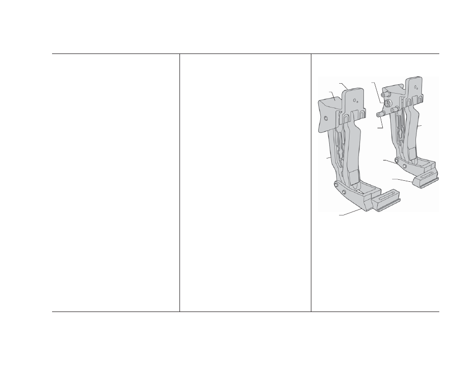
Service Tips
Linkage Component Identifi cation
Motor Gear
Shaft
Motor
Mounting
Boss
Mounting
Tab
Upper
Casting
Outer
Link
Inner
Link
Lower
Casting
Mounting
Foot
Motor
Linkage
Idler
Linkage
Pivot
Leg