Rough Country 674X User Manual
Page 9
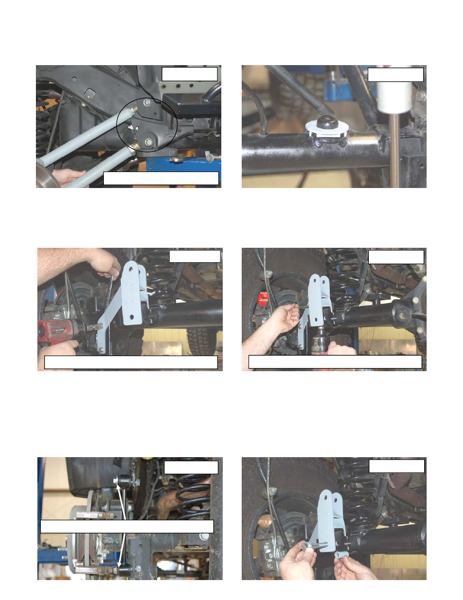
12. Assemble the heim joints in the new lower control arms and adjust them to a length of 20 1/2” from center of hole to
center of hole and tighten the jam nut using a 1 7/8” wrench. Install the hiem on the frame and the opposite end on
the axle with the factory hardware using a 21mm wrench. See Photo 23. Do not fully tighten.
13. Install the supplied rear coil shim as shown in Photo 24.
14. Install the supplied rear coil springs. Rotate the coils so that they seat properly in the coil seat, raise the axle
enough to seat the coil springs.
15. Install the supplied 3/8” x 1” Bolts , washers & flange lock nuts in the factory holes. Do not tighten. See Photo 25.
16. Using the track bar bracket as a template mark & drill a 13/32” hole in the top of the original track bar mount.
17. Install using the .375-16 x 1” bolt, washer through the drilled hole from the top and secure with flange nut using a
9/16” wrench and socket. See PHOTO 26.
18. Insert the supplied sleeve, inside the factory track bar mount. Insert the supplied 14mm” x 80mm” bolt through the
bracket, factory mount, and sleeve secure using the washer and nut. Do fully tighten. See Photo 27.
19. Tighten all track rod bracket hardware.
20. Install the factory track bar with the supplied 14mm x 75mm bolt washer & flange nut (upper hole) with the head of
the bolt on the front by the coil spring. The passenger side mount on the track bar will be installed in a later step.
21. Locate the 4 sway bar link sleeves. Insert the supplied 1/2” inner diameter sleeves into the sway bar link bushings.
Using the supplied .500-16 x 2.75” bolts, washers and nuts from 1681bag, install the sway bar links to the sway bar,
and axle mount., and tighten using a 13/16” socket and 7/8” wrench. See PHOTO 28. Make sure the bolts are
installed with the head of the bolt toward the tire as shown.
PHOTO 23
PHOTO 27
Install the lower control arms
Install washers on head of bolt
PHOTO 25
Position the bracket and install hardware
PHOTO 26
Install the 3/8” x 1” bolt in bracket
PHOTO 28
PHOTO 24